

Architectural Drawing Symbols: Complete Guide to Arch Symbols
Architectural drawing symbols are the universal language of construction. This complete guide covers all architect symbols—from electrical and lighting notation to material hatching patterns, HVAC symbols, and plumbing drawing symbols. Learn how to read, use, and master every architecture symbol in your building documentation.

Table of Contents Show
Quick answer: Architectural drawing symbols are standardized marks that represent real building elements on a plan, such as doors, windows, stairs, and electrical fittings. They let architects pack detailed information into a compact drawing that any builder can read, keeping construction documents consistent and clear.
Quick Answer: Architectural drawing symbols are standardized graphics that represent building elements – doors, windows, walls, stairs, fixtures, materials and dimensions – on technical drawings. They let architects, engineers and builders read plans consistently worldwide. Learning these symbols is essential to interpreting floor plans, sections and construction documents accurately.
Architectural drawing symbols are the universal language of the construction industry, serving as the essential communication tool between architects, engineers, contractors, and clients. These standardized architect symbols transform complex building information into clear, readable graphics that anyone in the industry can understand. Whether you’re examining construction drawing symbols on a floor plan or decoding electrical symbols in architecture, understanding this visual vocabulary is fundamental to successful project execution. In 2026 and beyond, mastering these symbols on drawings remains one of the most important skills for anyone involved in building design and construction.
Architectural drawing symbols are standardized graphic notations used in construction documents to represent building elements such as doors, windows, electrical outlets, lighting fixtures, structural members, and material types. Recognized worldwide by architects, engineers, and contractors, these symbols create a shared visual language that ensures accurate interpretation of floor plans, sections, elevations, and detail drawings across every phase of a building project.

From simple floor level indicators to electrical system notations, symbols on architectural drawings eliminate language barriers and reduce errors in construction documentation. Every architect and designer relies on these arch symbols to convey critical information efficiently, making them indispensable tools in modern building design and construction processes. In fact, architecture symbols are one of the first things students learn when entering the profession, as they form the backbone of all clear and readable architectural plans. Whether you call them drafting symbols, drawing symbols, or building drawing symbols, they all serve the same critical purpose: turning design intent into buildable reality.
Architectural drawing symbols play a significant function in any architectural drawing, contributing in the definition of components such as floor levels, lighting sources, and service areas. Electrical layouts, in particular, need a number of various objects and acronyms, and architect symbols drawings, when coupled by a key, give a simple way of identifying their placement, kind, and function. Understanding these drawing symbols and meanings is essential for every professional in the building industry.
Every architect needs symbols like this to indicate the main information in their drawings, however their appearance varies from company to company. They might be difficult for people who are not architect or civil engineer, but they are critical when attempting to imagine your finished project using a set of architectural drawings. Understanding symbols in architectural drawings is equally important for clients, contractors, and building inspectors who must interpret these documents accurately during the construction process. In this updated guide, we cover all essential architectural blueprint symbols, construction symbols and meanings, and the complete architecture legend you need to read any set of plans confidently.
Why Do We Use Architectural Drawing Symbols?
According to Michael Bell Architects, a renowned architect in Sydney, the use of architectural drawing symbols is a universal practice essential for all architects. These standardized symbols are recognized globally, despite slight variations that may exist due to different drawing styles. We will look at the significance of these symbols, offering insights into their application and understanding, thus underlining their role in the architectural profession.
The primary purpose of architecture symbols is to create a standardized visual language that transcends geographical and linguistic boundaries. According to the American Institute of Architects (AIA), consistent symbol usage reduces construction errors by ensuring all project stakeholders interpret drawings identically. This standardization is crucial in today’s globalized construction industry where international teams collaborate on complex projects. For professionals seeking a definitive reference on symbols on construction drawings, understanding these conventions is the first step.
These symbols, which are known all over the world, are used in technical drawings of architectural projects, representation of all service personnel in electrical projects, and lighting drawings. In the continuation of the article, we will see the symbols included in architectural technical drawings, symbols used in lighting drawings and electrical project drawings and which are largely universal. Beyond individual architect symbol recognition, understanding how these symbols work together as a system is what separates experienced professionals from beginners. This knowledge of symbolism in architecture extends beyond simple graphic recognition; it encompasses understanding how each symbol architecture convention communicates design intent.
📌 Did You Know?
The National Institute of Building Sciences (NIBS) maintains a standardized catalog of over 114 CAD symbols, each assigned a unique numeric code. These codes ensure that the same symbol carries the same meaning regardless of which software platform or drafting office produced the drawing.
Benefits of Standardized Drawing Symbols
Using consistent building drawing symbols across projects offers numerous advantages for architecture and construction professionals:
- Architectural symbols eliminate ambiguity and ensure all team members understand design intent
- Standardized architect symbols speed up both the drawing creation and interpretation processes
- Consistent symbol usage minimizes costly misinterpretations during construction
- Universal drawings and symbols enable cooperation between global teams
- Proper symbol application demonstrates industry expertise and attention to detail
- Standardized architectural drafting symbols help ensure drawings meet local building code requirements and pass review processes

Free Online Architectural Scale Converter
Architectural Scale Converter
Convert Real Size to Drawing Size
Enter the actual measurement and select a scale to find the drawing size.
Convert Drawing Size to Real Size
Enter the measurement on your drawing and select the scale to find the actual size.
Convert Between Scales
Convert a drawing measurement from one scale to another.
Find the Scale Ratio
Enter both real and drawing sizes to determine the scale used.
Unit Converter
Convert between metric and imperial units.
Architectural Technical Drawing Symbols and Plan Symbols Explained
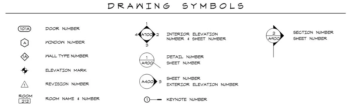
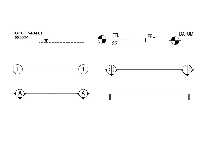
Architectural technical drawings primarily include plan and section drawings. The symbols architectural drawings contain for floor plans, master plans and site plans are almost the same for each country. The symbols you’ll see in the example below are architectural drafting symbols used to show levels on plans. You can show the elevation levels on the plans by choosing any of these symbols. These are also commonly referred to as drawing plan symbols or plan drawing symbols in practice.
Understanding drawing symbols architectural professionals use requires familiarity with several key categories. These include elevation markers, section cuts, door and window indicators, material hatching patterns, and dimensional notations. Each category serves a specific purpose in communicating three-dimensional design information on two-dimensional drawings. Learning to read these symbols of architectural drawings is an essential skill that architecture students develop early in their education, often alongside architectural sketching fundamentals. Whether referred to as architectural plan symbols or floor plan architecture symbols, these graphic conventions remain consistent in their purpose. For a deeper look at how section views work alongside plan symbols, see our guide to architectural section drawings.
Common Plan Symbols and Their Meanings
The most frequently encountered symbols of architectural drawings in floor plans include:
- Level Symbols: Indicate finished floor levels and datum points
- Section Markers: Show where vertical cuts through the building are taken (the section symbol architecture convention)
- Door Symbols: Represent swing direction, door type, and size
- Window Symbols: Indicate window placement, type, and operation
- Stair Symbols: Show stair direction, number of risers, and handrail locations
- North Arrow: Orients the drawing to geographical direction
These symbols on building plans and symbols on plans are the foundation of every readable set of construction documents. The architectural section symbol, a circle with an arrow indicating the viewing direction, is one of the most universally recognized drawing symbols in construction.

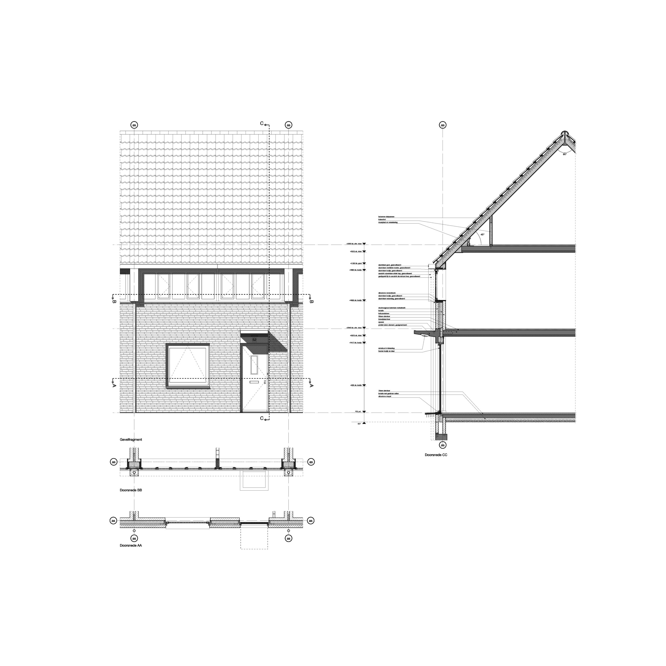
In the example below, you can see the symbols used in the roof, window sections and the view. Level symbols used in the plan are also in the same drawing language in the views and sections. For architects and engineers studying technical drawings, it is very important to prepare clear and understandable drawings. For this reason, the symbols you use should be simple and understandable, and consistent in terms of cross-sections and plans.
💡 Pro Tip
When reviewing a set of construction drawings, always check the symbol legend first before reading individual sheets. Firms often customize standard symbols with slight variations, and the legend is your definitive reference. A missing or outdated legend is one of the most common sources of on-site confusion, especially when subcontractors from different trades are reading the same drawing set.
Door and Window Symbols Explained
Among the most important architect symbols in any floor plan are those representing doors and windows. Door symbols typically show a quarter-circle arc indicating the swing direction, while the line represents the door leaf itself. Single doors, double doors, sliding doors, bi-fold doors, and revolving doors each have distinct drawing symbols architectural teams must recognize instantly. These house design symbols are critical for anyone reading residential house plan drawing symbols.
Window arch symbols vary based on the type of window specified. Casement windows, double-hung windows, fixed glazing, and operable windows all use different line configurations within the wall representation. Understanding these symbols on architectural drawings is critical for presenting architectural plans that contractors can follow without confusion.
Material and Hatching Symbols in Architecture
Material indication is a critical aspect of architectural drawing symbols that helps builders understand what materials are specified for different building components. Hatching patterns, the lines and patterns used to fill sectional areas, represent specific materials and follow industry standards established by organizations like the International Organization for Standardization (ISO). These material symbols in drafting are among the most important construction symbols that professionals must recognize.

Standard Material Hatching Patterns
Understanding material arch symbols is essential for reading construction documents accurately. Common hatching patterns include diagonal lines for brick, dotted patterns for concrete, and cross-hatching for earth or soil. These construction drawing symbols provide instant visual recognition of building materials specified in the design.
Key material symbols every architect should recognize include representations for concrete (both cast-in-place and precast), various types of masonry, steel sections, wood grain directions, insulation, and waterproofing membranes. Each symbol has been carefully designed to be distinct and easily recognizable even at small scales. These material architectural symbols are often among the first architectural drafting symbols that students learn in technical drawing courses. Collectively, they form an essential part of the architecture diagram signs and symbols vocabulary.
📐 Technical Note
ISO 128-50 defines the general principles for hatching in technical drawings, while ANSI/ASME Y14.2 covers line conventions and lettering for U.S. practice. When working on international projects, verify which standard governs your drawing set, as hatching angle and spacing conventions can differ between ISO and ANSI systems.
Complete Material Symbol Reference
For professionals working with construction drawing symbols, here is a reference of standard material representations used in section and detail drawings:
Concrete is represented by a pattern of triangular dots, while reinforced concrete adds diagonal lines to the dot pattern. Structural steel sections are shown as solid filled shapes, and architectural abbreviations like “STL” or “CONC” often accompany these symbols for additional clarity. These building construction drawing symbols are standardized across most international codes.
Brick masonry uses a 45-degree diagonal line pattern, concrete block (CMU) uses a different angled pattern, and natural stone is represented by an irregular pattern. These building drawing symbols help contractors quickly identify wall construction methods and are a core part of building construction symbols documentation.
Wood is shown with a grain pattern, plywood with alternating line directions at each layer, and gypsum board with a stippled pattern. Insulation has a unique cloud-like or scalloped pattern that makes it instantly recognizable in any architect symbols drawings document. Knowing these drawing symbols meaning conventions ensures accurate material takeoffs and cost estimation.

Lighting Drawing Symbols and Architectural Lighting Plan Symbols
Lighting elements have a very important role, especially for interior drawings. It is possible with these architectural symbols to show which lighting type is selected in the technical drawings and what features it has in the project. Examine the table of lighting elements where you can see all types in the image below. You can draw lighting types in your projects by preparing the DWG formats of these symbols or using the ready-made symbols. Light symbols for floor plans are essential for communicating the complete lighting design intent to electricians and contractors.
Modern architect symbols drawings for lighting have evolved to include LED fixtures, smart lighting systems, and emergency illumination. The Illuminating Engineering Society (IES) provides guidelines for lighting symbol standards that ensure consistency across the industry. These architectural lighting plan symbols are updated regularly to reflect new fixture technologies and energy codes in 2026 and beyond.
You can prepare a legend similar to the table below to show which symbol corresponds to which lighting type in the project drawings. Do not forget that the symbols and texts you will use in the legend are legible, it is extremely important for your field colleagues who will implement your project. A well-prepared drawing legend, also called an architecture legend, is one of the most important reference tools on any lighting plan sheet. Understanding symbols for interior design lighting layouts is equally critical for interior designers collaborating on projects.
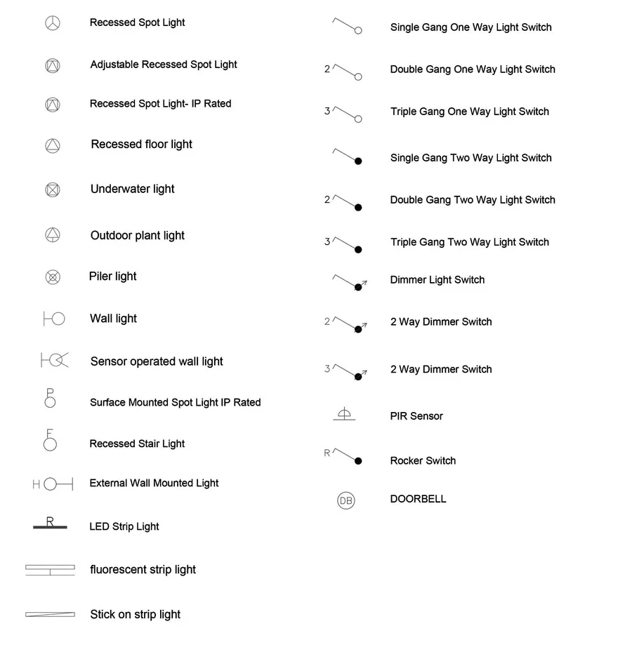
Types of Lighting Symbols
The most common symbols on architectural drawings for lighting include:
- Recessed Downlights: Typically shown as circles with an “R” or specific fixture code
- Surface-Mounted Fixtures: Represented by squares or rectangles with fixture designation
- Pendant Lights: Shown with a circle and hanging line indicator
- Track Lighting: Depicted as a line with attached fixture symbols
- Emergency Lighting: Often marked with “EM” or specific emergency symbols
- Exit Signs: Indicated with standardized exit symbol markers

Electrical Drawing Symbols: Architect Electrical Symbols Explained
Next are the electrical symbols in architecture that drawings require for documentation. These signs are used all over the world to symbolize all electrical elements and electronic connections included in the architectural project. You have to use these architect symbols to represent every element in your plan drawings, from electrical sockets to TV connections to electrical panels. Understanding electrical symbols architectural conventions is non-negotiable for producing code-compliant drawings.
Since you, as an architect, have covered every detail, or rather every point, of your projects, the best way to convey these details is to use symbols. With electrical drawing symbols, you can show the types of electrical socket in the room and location of electrical panels or any detector that you have decided. These architect electrical symbols are a vital subset of the broader architectural blueprint symbols library. For a deeper understanding of electrical notation, explore our dedicated guide to electrical blueprint symbols.
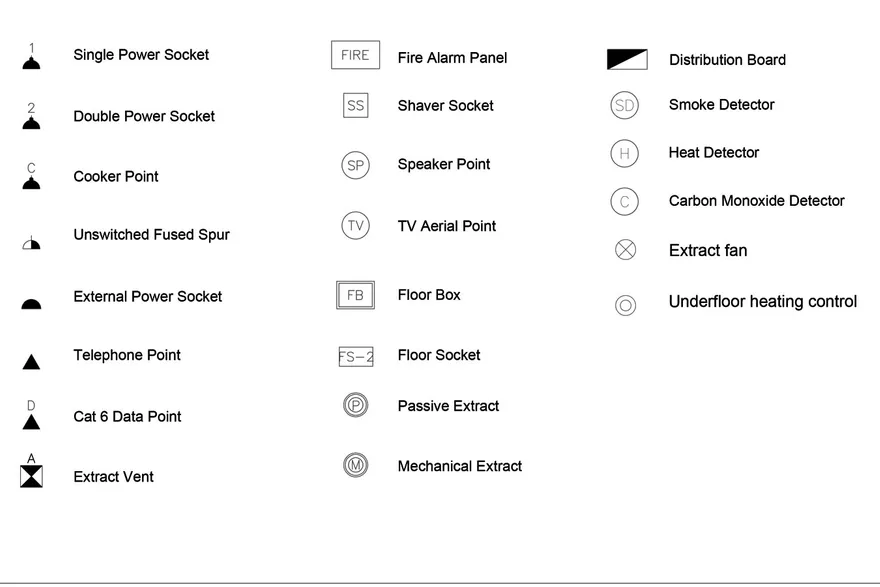
Essential Electrical Symbols for Architects
Understanding electrical symbols in architecture is crucial for coordinating with electrical engineers and contractors. The National Electrical Code (NEC) provides standardized symbols that ensure safety and consistency in electrical documentation.
Key building drawing symbols for electrical systems include:
- Duplex Receptacles: Standard wall outlets shown as circles with parallel lines
- GFCI Outlets: Ground fault circuit interrupter outlets with specific marking
- Light Switches: Single-pole, three-way, and dimmer switches each have unique symbols
- Electrical Panels: Distribution panels and breaker boxes with load schedules
- Data/Communication Outlets: Television, telephone, and network connections
- Smoke and Carbon Monoxide Detectors: Life safety devices with standardized notation
⚠️ Common Mistake to Avoid
A frequent error in multi-discipline projects is mixing NEC (North American) and IEC (European) electrical symbols on the same drawing set. For example, the standard outlet symbol differs significantly between these two systems. Always confirm which symbol standard applies at the project kickoff and document it in the legend sheet. Using the wrong standard can cause electricians to install incorrect fixture types, leading to costly rework and potential code violations.
Understanding Electrical Symbol Variations Across Standards
One important consideration when working with electrical symbols in architecture is that notation can vary significantly between different regional standards. North American electrical architect symbol conventions follow NEC guidelines, while European projects typically adhere to IEC (International Electrotechnical Commission) standards. For instance, a standard outlet symbol in the United States uses a circle with two parallel lines, whereas European standards may use different representations for the same component. When working on international projects, always clarify which architectural drawing symbols standard applies before beginning documentation. This is especially important when coordinating symbols for construction drawings across multinational teams.

HVAC and Mechanical Symbols
Mechanical systems require their own set of architectural drafting symbols to communicate heating, ventilation, and air conditioning requirements. These architecture symbols work in conjunction with electrical and plumbing symbols to create building documentation that covers every system.
HVAC symbols of architectural drawings include representations for supply and return air diffusers, thermostats, ductwork, mechanical equipment, and control systems. Proper symbol usage ensures that mechanical contractors can accurately install systems according to design specifications. The American Society of Heating, Refrigerating and Air-Conditioning Engineers (ASHRAE) publishes guidelines that influence HVAC symbol standards worldwide. These engineering symbols for drawings are essential for coordinating MEP systems effectively.
Common HVAC Symbols
- Supply Air Diffuser: Typically shown as a square with directional arrows
- Return Air Grille: Represented by a grid pattern within a rectangle
- Thermostat: Small circle or rectangle with “T” designation
- Ductwork: Shown as parallel lines with directional flow arrows
- Mechanical Units: Equipment symbols with model designations

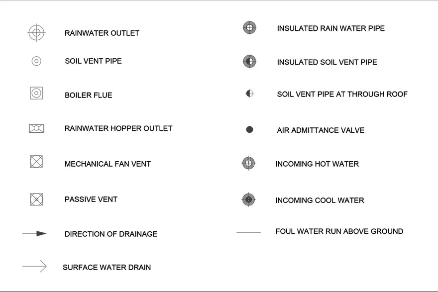
Plumbing Drawing Symbols
Plumbing construction drawing symbols represent water supply, drainage, and fixture locations throughout a building. These architect symbols drawings follow standards established by plumbing codes and industry organizations to ensure proper system installation and function.
Understanding plumbing drawing symbols architectural teams use enables coordination between architecture, structural, and MEP (mechanical, electrical, plumbing) disciplines. Fixture symbols show sinks, toilets, showers, and specialty equipment, while pipe symbols indicate supply and waste line routing. Proper coordination of plumbing symbols in architectural drawings with other building systems is essential for avoiding costly clashes during construction. These symbols of building systems are increasingly managed through BIM coordination in modern practice.
Key Plumbing Symbols to Know
The most important plumbing arch symbols that architects and designers should recognize include those for hot and cold water supply lines (typically shown as solid and dashed lines respectively), waste and vent pipes, cleanouts, valves, and fixture connections. Fire suppression systems also use specific building drawing symbols that must be coordinated with the overall plumbing and fire protection documentation. These plumbing symbols on building plans are a critical component of the symbol of building construction documentation package.
Structural Drawing Symbols
While often produced by structural engineers, architectural drawing symbols for structural elements are essential knowledge for every architect. Structural symbols architectural drawings contain include column grids (identified by letters and numbers), beam callouts, footing symbols, and load-bearing wall indicators. These architect symbols help communicate the building’s skeleton and ensure that architectural elements align with structural requirements.
Understanding structural symbols on architectural drawings is particularly important when working with architectural detail drawings, where the intersection of architectural and structural components must be clearly documented. Column symbols, for instance, are typically shown as filled circles or rectangles at grid intersections, and their dimensions and reinforcement details are referenced through callout architect symbol notation. These structural symbols drawings are part of the complete drawings symbol vocabulary that every design professional should master.
Site Plan Symbols
Site plan architecture symbols communicate information about the broader context of a building project. These construction drawing symbols include property boundary lines, setback indicators, topographic contour lines, vegetation symbols, and utility connection points. Understanding site plan architectural symbols is crucial for reading and interpreting plot plans accurately.
Common site plan drawing symbols architectural teams encounter include representations for existing trees (circles with cross patterns), proposed landscaping, parking layouts, fire hydrant locations, and drainage patterns. These symbols of architectural drawings provide essential context about how a building relates to its surroundings and to municipal infrastructure. In essence, site plan architecture symbols on drawings establish the project’s relationship with its environment and regulatory framework.
What Are the Symbols for a Set of Plans Located? Understanding the Drawing Legend
One of the most common questions beginners ask is: what are the symbols for a set of plans located? The answer is the drawing legend, also known as a symbol key or architecture legend. Every complete set of construction documents includes a legend sheet, typically found on the first or second page of each discipline’s drawing set (architectural, electrical, mechanical, plumbing). This legend lists every architect symbol used in the project alongside its description, ensuring that anyone reading the plans can decode the construction symbols on drawings without ambiguity.
The drawing legend typically includes categorized sections for general architectural plan symbols, material hatching patterns, electrical symbols architectural conventions, plumbing fixtures, and HVAC components. A well-organized legend is the key to understanding any symbols on plans across the entire document set. For complex projects, each discipline may have its own dedicated legend sheet with discipline-specific drawing symbols and meanings.
Symbols for Interior Design on Architectural Drawings
Interior designers rely heavily on symbols for interior design when documenting furniture layouts, finish schedules, and fixture specifications. These architect symbols on plans include representations for furniture pieces (sofas, tables, beds), built-in cabinetry, appliances, and decorative elements. Interior design symbols in drawings also cover finish material indicators, wall treatment notations, and specialty items like fireplaces and built-in shelving.
Understanding these architectural symbols bridges the gap between architectural and interior design documentation. Interior-specific drawing symbols for elements like carpet transitions, tile patterns, and millwork details ensure that design intent is precisely communicated from the studio to the job site. For interior designers working with floor plan presentations, mastering these floor plan symbols explained conventions is essential for professional documentation.
Iconography in Architecture: The History and Meaning of Symbols
The concept of iconography in architecture extends beyond simple technical notation. Architectural symbolism in architecture has deep historical roots, from ancient Egyptian hieroglyphic building records to the codified drawing standards we use today. The evolution of symbol for architecture reflects the development of the profession itself, with each era contributing new conventions as building technologies advanced.
Today’s architectural drawing symbols are the product of centuries of refinement. The modern symbol for architect documentation emerged primarily in the 19th and 20th centuries, as the profession formalized its practices through organizations like the AIA and RIBA. Understanding this rich heritage of symbols of architecture gives practitioners a deeper appreciation for the visual language they use daily. The architecture symbol conventions we now take for granted were developed through decades of collaborative standardization.
Digital Tools for Architectural Symbols
Modern CAD and BIM software has transformed how architects work with architectural drawing symbols. Programs like Autodesk Revit, AutoCAD, and ArchiCAD include extensive symbol libraries that comply with international standards. These digital tools enable architects to maintain symbol consistency across large project document sets. For a broader overview of architectural design software and their features, our dedicated guide provides additional context.
When selecting CAD blocks or creating custom arch symbols, architects should ensure symbols are scalable, properly attributed, and consistent with project standards. Many firms develop custom symbol libraries that reflect their specific documentation requirements while maintaining compliance with industry norms. In 2026, AI-assisted drafting tools are beginning to automate symbol placement, though professional review of all symbols in drawing outputs remains essential.
BIM and the Future of Architectural Symbols
Building Information Modeling (BIM) is reshaping how architect symbols drawings are created and managed. Unlike traditional 2D architectural drafting symbols, BIM-based symbols carry intelligent data about the elements they represent. A door symbol in Revit, for example, contains information about dimensions, material, fire rating, hardware, and cost, far beyond what traditional architecture symbols could convey.
This evolution means that modern architectural symbols serve dual purposes: visual communication on printed drawings and data carriers in digital models. As BIM adoption increases globally, the relationship between visual symbols in architectural drawings and their embedded data becomes increasingly important for project coordination and facility management. Recent updates to buildingSMART International’s IFC standards further standardize how construction symbols translate between different software platforms.

Reading Architectural Drawings: Floor Plan Symbols Explained
For those learning to interpret symbols architectural drawings contain, developing systematic reading habits is essential. Start by identifying the drawing title, scale, and north orientation. Then locate the legend or symbol key, which provides project-specific symbol definitions. Finally, trace systems from their origin points to understand how building components connect. This process applies whether you’re reading floor plan symbols explained guides or decoding a full set of construction symbols on drawings.
Professional architects recommend reviewing drawings and symbols in a specific order: site plan, floor plans, elevations, sections, and finally detail drawings. This progression helps build a mental model of the building before examining specific construction details. Additionally, understanding architectural abbreviations that accompany these symbols helps complete the picture, as architect symbols and abbreviations often work together to provide full specification information. Learning both drawing symbols meaning and abbreviation codes simultaneously will accelerate your ability to read any set of plans.

Understanding Drawing Scales and Symbol Sizes
The scale of a drawing directly affects how architectural drawing symbols appear and should be interpreted. At larger scales (such as 1:50 or 1/4″ = 1′-0″), architect symbols show more detail and specific information. At smaller scales (such as 1:200 or 1/16″ = 1′-0″), symbols become more simplified and schematic. Professionals must be able to read symbols in architectural drawings at any scale and understand that the same element may be represented differently depending on the drawing’s level of detail.
International Standards for Architectural Symbols
While architectural symbols are largely universal, regional variations exist that architects working internationally must understand. The ISO provides international guidelines, while organizations like the Royal Institute of British Architects (RIBA) and AIA publish regional standards.
Key differences in symbols on architectural drawings between regions include electrical symbol variations (particularly between North American and European standards), metric versus imperial dimensioning, and material hatching conventions. Architects working on international projects should always clarify symbol standards during project initiation. These differences affect everything from construction symbols and meanings to how symbols are documented across borders.
Regional Symbol Standards Comparison
When comparing architectural drawing symbols across different standards, several key distinctions emerge. North American practices largely follow ANSI/ASME standards, where construction drawing symbols use imperial measurements and specific notation conventions. European standards, governed by ISO and EN norms, employ metric notation and different architect symbol representations for many common elements.
The British Standards Institution (BSI) publishes BS 1192 (now superseded by BS EN ISO 19650) which provides guidelines for architectural drafting symbols used in British practice. Similarly, the Australian Standards (AS 1100) and Japanese Industrial Standards (JIS) each define their own conventions for symbols architectural drawings should follow.

Common Mistakes When Using Architectural Drawing Symbols
Even experienced professionals occasionally make errors with architectural drawing symbols. Recognizing these common mistakes helps improve drawing quality and reduce construction issues:
Using different architect symbols for the same element across drawing sheets is one of the most common errors. This creates confusion and can lead to construction mistakes. Establishing a project symbol standard at the outset prevents this problem.
Every set of construction drawing symbols should include a legend. Omitting the legend or failing to update it when new architecture symbols are added to the drawings creates interpretation difficulties for contractors.
Using arch symbols sized for one scale on a drawing of a different scale makes documents difficult to read. Always verify that drawing symbols architectural teams use are appropriately scaled for each sheet.
Using obsolete architectural drafting symbols that no longer comply with current standards can cause compliance issues. Regularly updating symbol libraries ensures your symbols in architectural drawings meet current code requirements. With updated codes in 2026, keeping your drawing symbols construction library current is more important than ever.
Best Practices for Using Architectural Symbols
Effective use of architectural drawing symbols requires attention to several key principles:
- Use the same symbol for the same element throughout all project drawings
- Ensure symbols are appropriately sized and clearly visible at the intended print scale
- Always include a legend explaining all architect symbols used
- Follow industry standards appropriate for the project location
- Verify symbol usage with consultants and contractors before construction
- Keep symbol libraries current with evolving industry standards and new building technologies
- Ensure all team members understand the symbols on architectural drawings used in your firm’s standard practices

Symbol Templates and Resources for Architects
Architects looking to build or expand their architectural drawing symbols library have several excellent resources available. Most CAD and BIM platforms offer built-in symbol libraries, but many professionals supplement these with third-party collections and custom-created architect symbols.
Physical drafting templates, though less common in the digital age, remain valuable for quick sketches and field markup. These templates typically include standard arch symbols for doors, windows, plumbing fixtures, electrical devices, and furniture at various scales. Digital resources include manufacturer-specific BIM families that contain detailed architecture symbols matched to real products. Websites like ArchDaily and Dezeen regularly feature resources and articles discussing the latest developments in architectural documentation, including emerging symbols on drawings conventions.
For those looking to improve their architectural drawing skills, practicing with standard architectural drafting symbols is an excellent starting point. Understanding how to draw and interpret these symbols in architectural drawings forms the foundation for producing professional-quality documentation.
How to Create Your Own Architectural Symbol Library
Building a custom symbol library is a practical step that saves time across every project. Whether you work in AutoCAD, Revit, or ArchiCAD, the process follows a similar logic: start by collecting the standard symbols your firm uses most frequently, then organize them into categorized blocks or families.
Begin with the symbols you place on every drawing: north arrows, section markers, elevation tags, door and window types, and level indicators. Create each symbol at a 1:1 scale so it can be inserted into any drawing and scaled as needed. Group related symbols into folders or palettes by discipline (architectural, electrical, mechanical, plumbing) so team members can find what they need quickly.
For BIM-based workflows, each symbol should carry embedded parameters. A door family in Revit, for example, should include fields for fire rating, acoustic rating, hardware set, and finish material. This turns every symbol into both a graphic element and a data container, supporting accurate schedules and quantity takeoffs.
💡 Pro Tip
Experienced firms assign one team member as the “standards manager” responsible for maintaining and updating the symbol library. This person reviews new symbols before they enter the library, checks them against current codes, and removes outdated versions. Without this role, symbol libraries tend to grow cluttered with duplicate or inconsistent blocks that slow down production.
Document your library with an internal reference sheet that shows each symbol alongside its name, scale, and intended use. Share this reference during onboarding so new team members produce consistent drawings from their first project. A well-maintained library, combined with clear documentation, is one of the most effective ways to improve drawing quality across an entire office. For more on the technical side of architectural drawing and sketching techniques, our separate guide covers the fundamentals.
✅ Key Takeaways
- Architectural drawing symbols are standardized graphic notations that form the shared language of the construction industry across all disciplines
- Every drawing set must include a legend sheet that defines all symbols used in the project to prevent misinterpretation
- Material hatching, electrical, lighting, HVAC, and plumbing symbols each follow their own conventions governed by ISO, ANSI, IEC, or regional standards
- BIM-based symbols carry embedded data beyond their visual representation, serving both graphic and informational purposes
- Always verify which regional symbol standard applies before starting documentation on international projects
- Maintaining a consistent, up-to-date symbol library with clear internal documentation reduces errors and speeds up production across every project
Conclusion: Mastering Architectural Drawing Symbols
Mastering architectural drawing symbols is fundamental to success in architecture, engineering, and construction. These architecture symbols form the visual vocabulary that enables clear communication across disciplines and international boundaries. Whether you’re interpreting electrical symbols in architecture, creating construction drawing symbols for new projects, or decoding architect floor plan symbols for a renovation, understanding this standardized language is essential.
As building technologies evolve and projects become more complex, the importance of consistent, clear symbols of architectural drawings only increases. By following established standards and maintaining symbol consistency, architects ensure their designs are accurately communicated and successfully constructed. From architect symbol basics to complex system notation, every professional in the building industry benefits from a thorough understanding of this visual language. Whether you work with symbols in drafting on a daily basis or are just learning to read house plan drawing symbols, the knowledge in this guide will serve you throughout your career.
Continue developing your understanding of architectural drafting symbols by exploring our related guides on electrical blueprint symbols, 10 common architectural symbols and their meanings, and architectural design principles.
Related Guides
- Unlocking the Power of Architectural Grids: A Guide to Design and Harmony
- Architecture Plan: Tips for Creating & Presenting Plans
More Related Guides
- What Is Architectural Casework
- What Is Architectural Brief
- Understanding Building Layout
- Arkdesign Ai Review From Brief To Building Code Compliant Schematic Design In One Click
- Best Elevation Drawings
- The Future Drawing Up The Bathroom
- Brandenburg Gate Political Symbol
- Blueprints Budgets Navigating Architectural Project Financing
- Open Plan Vs Closed Plan
- Honest Guide Powering Furnishing Home Off Grid
Frequently Asked Questions
What are the most common architectural drawing symbols?
Common symbols include doors shown as an arc, windows as parallel lines in a wall, stairs as numbered treads with a direction arrow, and fixtures such as sinks and toilets drawn in plan. Electrical symbols mark outlets, switches, and lights.
Why do architects use symbols instead of full drawings?
Symbols let architects pack detailed information into a compact, readable drawing. A shared symbol language means any builder or engineer reads the plan the same way, which reduces errors on site.
Are architectural drawing symbols standardized?
Many symbols follow national and international standards such as those from the AIA and ISO, although offices often keep their own legend. A symbol key on the drawing set removes any ambiguity.
Last updated:


3 Comments


Porch Enclosures: Why Clear Vinyl Systems Are the Smart Choice for Year-Round Outdoor Living
Homeowners are finding new ways to enjoy their outdoor spaces without committing...

Why Is the Architecture Physical Model Still Taught in Schools?
Digital tools run modern architecture, yet schools still put students at the...

Schematic Design and Design Development: Key Differences Explained
Schematic design and design development are sequential architectural phases that answer different...

The 10 Longest Bridges in the World
The world's longest bridges are dominated by Asian high-speed rail viaducts, led...

I think the article explains symbols used in architecture clearly. It seems important for everyone in construction to understand these symbols, even if it can be a bit hard for beginners.
This article talks about architectural drawing symbols. It explains why they are important for builders and designers. I think it’s helpful for those in the construction industry.
I found the article informative. It explains why understanding architectural symbols is important for everyone in the construction field. The examples of different symbols were helpful.