

Architecture Plan: Tips for Creating & Presenting Plans
Learn how to create and present professional architectural plans with this comprehensive guide. From defining what an architecture plan is to step-by-step drawing instructions, essential software tools, and presentation best practices, this article covers everything architects need to produce effective floor plans and building plans.

Table of Contents Show
Quick answer: An architectural plan is a scaled drawing that shows a building seen from above, mapping walls, rooms, doors, and dimensions. It guides construction and communicates the layout to clients and builders, using clear line weights, symbols, and annotations so it can be read at a glance.
In architecture, there are many types of architectural plans that professionals must master. From small-scale detail drawings to large-scale master plans, an architectural plan serves as the foundational document for every construction project. Architects are responsible for creating and presenting various plan types, including site plans, floor plans, ceiling plans, roofing plans, and more.
When designing and constructing a project, the architectural floor plan is the most crucial drawing in the set. A smart floor design fosters pleasant flow between spaces, boosting both the enjoyment of a home and its property value. Whether you are a student learning how to make architectural drawings or a professional refining your architectural planning skills, understanding the principles behind creating effective plans is essential.
An architectural plan is a scaled technical drawing that shows the layout, dimensions, and spatial organization of a building from a top-down view. It is taken as a horizontal cross-section about 1.2 meters (4 feet) above floor level and serves as the primary communication tool between architects, engineers, builders, and clients across every stage of a construction project.
What Is an Architectural Plan? Definition and Types
Before getting into the creation process, it helps to understand the architecture plan definition. An architectural plan is a scaled, technical drawing that represents the layout, dimensions, and spatial organization of a building or structure. It is a horizontal cross-section typically taken about 1.2 meters (4 feet) above the floor level, showing walls, doors, windows, and other built elements from a bird’s-eye perspective.
Architectural drawing plans come in several types, each serving a specific purpose in the design and construction process:
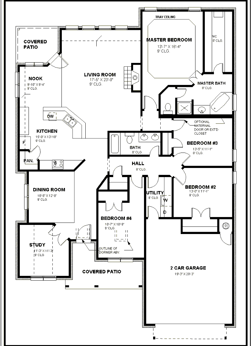
Floor Plans: The most common type of architecture plan drawing, showing the room layout, wall positions, doors, and windows for each level of a building. Floor plans are essential for understanding the spatial organization and flow of a space.
Site Plans: These architectural site plans show the building’s position on the property, including boundaries, landscaping, access roads, and utility connections. A well-prepared site plan is a requirement for most planning permission applications.
Ceiling Plans: Also known as reflected ceiling plans (RCP), these show ceiling materials, lighting fixture locations, and mechanical elements when viewed from above.
Roof Plans: These illustrate the roof structure, drainage direction, slopes, and materials from a top-down view.
Architectural Building Plans: A full set that includes all of the above, plus elevations, sections, and detail drawings needed for permit approvals and construction.
Understanding these types is the first step in architectural planning. Each plan type communicates specific information to builders, engineers, clients, and regulatory authorities, ensuring that design intent translates accurately into the built environment.
📌 Did You Know?
The convention of cutting a floor plan at 1.2 meters (4 feet) above floor level dates to Renaissance-era orthographic projection standards. At this height, the cut consistently captures windows, doors, and counter-height elements while missing ceiling-mounted fixtures, which is why a separate reflected ceiling plan exists as a distinct drawing type.
To understand how all these drawing types coordinate, our guide on how elevations, floor plans, and sections work together explains the relationships in detail.
Architectural Plan vs. Floor Plan: What Is the Difference?
This is one of the most common questions architects and students ask. An architectural plan is a broad term covering all scaled drawings used in building design, including floor plans, site plans, ceiling plans, roof plans, elevations, and sections. A floor plan refers specifically to the horizontal cross-section of a single building level.
In short: every floor plan is an architectural plan, but not every architectural plan is a floor plan.
| Plan Type | What It Shows | Typical Scale | Primary Use |
|---|---|---|---|
| Floor Plan | Room layout, walls, doors, windows (one level) | 1:50 or 1:100 | Spatial layout, client approvals |
| Site Plan | Building position on plot, landscaping, access | 1:200 or 1:500 | Planning permission submissions |
| Reflected Ceiling Plan | Ceiling materials, lighting, mechanical elements | 1:50 or 1:100 | MEP coordination, interior fit-out |
| Roof Plan | Roof structure, drainage, slopes, materials | 1:100 or 1:200 | Structural documentation |
| Building Plan Set | All views: plans, elevations, sections, details | Multiple | Construction documentation |
How Do You Read an Architectural Plan?
Reading an architectural plan requires familiarity with standard architectural drawing symbols and the logic of orthographic projection. Here are the key elements to look for:
Walls: Shown as thick lines (or two parallel lines with hatching). Exterior walls are typically thicker than interior partitions.
Doors: Represented by a thin line (the door) and a quarter-circle arc showing the swing direction. Sliding doors use parallel lines.
Windows: Three parallel lines within a wall opening. The symbol changes slightly depending on the window type (casement, fixed, sliding).
Room labels and dimensions: Room names, floor areas (in square meters or feet), and critical dimensions appear inside each space.
North arrow and scale bar: Always located in the title block or drawing margin, these confirm orientation and proportional accuracy.
To understand how architectural scale works in practice, including converting between drawing measurements and real-world dimensions, our dedicated scale guide covers both metric and imperial systems.
⚠️ Common Mistake to Avoid
A frequent error when reading floor plans is confusing a reflected ceiling plan (RCP) with a standard floor plan. The RCP shows what you would see if you lay on the floor and look up, meaning it shows ceilings, not floors. Always check the drawing title block before interpreting symbol locations, especially for lighting and HVAC elements.
How to Make Architectural Drawings: Step-by-Step Guide

Creating an effective architectural plan requires a methodical approach. Whether you are working on a new construction or documenting an existing building, follow these steps to draw an architectural drawing that is accurate, clear, and professional.
Step 1: Define the Drawing Area and Scope
Start by deciding what to draw and how much of it to capture.
If the building already exists, choose how much of it to depict: a single room, one floor, or the whole building. If the structure is yet to be built, develop ideas based on the size and shape of the site. At this stage, reviewing bubble diagrams can help you organize spatial relationships before committing to a detailed plan.
Step 2: Measure and Document Existing Conditions
If the building exists, measure walls, doors, and relevant furnishings to ensure the floor layout is accurate. Use professional measuring tools such as laser distance meters, measuring tapes, and architectural scales. Accurate measurements are the foundation of every reliable architectural drawing floor plan.
💡 Pro Tip
When surveying an existing building, always take three measurements of the same wall from different points and use the average. Walls are rarely perfectly straight, and a single measurement at one end can be off by 20–30 mm over a 5-meter span. That kind of error compounds quickly when you add room after room.
Step 3: Verify Dimensions and Research Costs
If the layout is being designed for a new area, confirm the entire program fits within the available site. Studying buildings constructed in nearby neighborhoods helps estimate realistic costs. Following established standards from organizations like the American Institute of Architects (AIA) ensures your drawings meet professional expectations.
Step 4: Draw the Walls to Scale
Start with the walls. Add each room to the building, drawing walls to scale from the outset. Whether you use traditional drafting or CAD software like AutoCAD, accurate wall thicknesses and proportions are critical. Exterior walls are typically drawn thicker than interior partition walls to reflect actual construction dimensions.
📐 Technical Note
In most residential construction, exterior cavity walls are drawn at 300–350 mm thick, internal load-bearing walls at 200–225 mm, and non-structural partitions at 100 mm. These are typical UK/EU dimensions; North American framing conventions differ. Always confirm local standards and structural requirements before finalizing wall thicknesses in your architectural plan.
Step 5: Add Architectural Details
Include fixed elements such as doors and windows, along with appliances and other items that must occupy a precise position (refrigerators, dishwashers, structural columns). Doors should show their swing direction, and windows should indicate their type (casement, sliding, fixed). These details transform a basic architecture layout into a functional construction document. For a thorough grounding in reading and applying these conventions, our guide on creating clear and readable architectural plans is a useful next step.
Step 6: Place Furniture and Interior Elements
Once the fixed elements are placed, add furniture. Furniture layout helps clients and stakeholders visualize how the space will be used in daily life. For more guidance on furnishing layouts, explore things to consider when designing a floor plan.
Free Online Architectural Scale Converter
Convert Real Size to Drawing Size
Enter the actual measurement and select a scale to find the drawing size.
Convert Drawing Size to Real Size
Enter the measurement on your drawing and select the scale to find the actual size.
Convert Between Scales
Convert a drawing measurement from one scale to another.
Find the Scale Ratio
Enter both real and drawing sizes to determine the scale used.
Unit Converter
Convert between metric and imperial units.
Key Considerations for Architecture Plan Design
Creating a good architectural plan means balancing practical issues with design intent. Before committing to a particular layout, consider safety, maintenance, and long-term energy costs alongside aesthetics.
Beyond the basics, successful architectural planning also requires attention to:
Building codes and regulations: Every architectural plan must comply with local building codes, fire safety regulations, and accessibility requirements such as those outlined by the Royal Institute of British Architects (RIBA) or similar bodies in your region.
Structural feasibility: Your plan should account for load-bearing walls, column positions, and structural spans that an engineer will verify during construction documentation.
Sustainability and energy efficiency: Modern architectural plans increasingly incorporate passive design strategies such as optimal window orientation for natural light, cross-ventilation pathways, and insulation specifications. The American Society of Heating, Refrigerating and Air-Conditioning Engineers (ASHRAE) publishes widely referenced energy performance standards that inform these decisions.
Circulation and flow: The architectural layout should ensure logical movement patterns between rooms, with clear corridors and no dead-end spaces. Good circulation separates a functional plan from a confusing one.

Essential Software and Tools for Architecture Drawing Plans
In 2026, architects rely on a range of digital tools to create accurate and professional architectural drawing plans. Choosing the right software depends on your project’s scale, experience level, and the type of output you need. Here are the most widely used tools:
AutoCAD: The industry-standard 2D drafting tool, ideal for precise plan architecture drawings with accurate dimensions and annotations.
Revit: A BIM (Building Information Modeling) platform that connects floor plans to 3D models, schedules, and construction documentation automatically. Autodesk Revit is the market-leading BIM solution used by most large architecture firms worldwide.
ArchiCAD: A popular alternative to Revit, with strong BIM capabilities and an interface favored by many European architects.
SketchUp: A versatile 3D modeling tool excellent for quick conceptual designs and creating house blueprints. The official SketchUp website offers tutorials and extensions specifically designed for architectural workflows.
Adobe Photoshop and Illustrator: Essential for post-production work on architectural plans, including adding textures, colors, and presentation-ready graphics. For a full overview of architectural design software and features, check our dedicated guide.
If you want to learn how to draw an architectural drawing using these tools, many online platforms offer specialized courses. Investing in software skills directly impacts the quality of your architectural building plans.
💡 Pro Tip
If you are starting out with BIM software, begin with a single-room model before tackling a full floor plate. Learning to set up a correct level system, wall types, and sheet setup in Revit or ArchiCAD on a small project saves hours of rework later. Most errors in architectural plan sets trace back to incorrect level or wall-type setup done in the first hour of the project.
Presenting an Architectural Plan

After creating a correct architectural plan, you need to present your designs effectively. We have a dedicated article on “How to Present Better Architectural Plans” that covers presentation strategy in depth.
Software knowledge and an understanding of architectural detail both matter for strong presentations. If you need to develop skills in Adobe Photoshop or Illustrator, online courses are widely available. Understanding the principles of architectural detail drawing also raises the quality of plan presentations.

Strong architectural presentations depend on quality drawings and renders. Plans should be clear, legible, and self-explanatory. Clients and jury members evaluate 3D visuals alongside architectural floor plans, so both outputs need attention. To sharpen your overall drawing ability, read our guide on improving architectural drawing skills.
Floor plans are supporting elements of any full presentation. They communicate spatial organization and layout to everyone interested in the project. The site plan and ground floor plan describe the building’s entrance and its relationship to the street, while upper floor plans show how life unfolds within the space. A well-organized set of plans, combined with successful section drawings, gives a complete picture of the design. For context on how these drawing types relate, see our overview on architectural programmes and functions diagrams.

When presenting an architectural plan, make sure colors are consistent and that items, dimensions, and lines read clearly. As shown in the examples above, floor covering choices, color decisions, and the plan’s relationship to its context all shape how viewers perceive the design. Learning to organize your architectural plans effectively raises presentation quality.
Tips for Better Architecture Plan Presentations
To create architecture design plans that impress clients, juries, and stakeholders, keep these points in mind:
Use consistent line weights: Differentiate between cut elements (walls), elements in projection, and elements beyond the cut plane using varying line thicknesses. This hierarchy makes your plan architecture drawing easier to read.
Apply a cohesive color palette: Choose colors that complement each other and clearly distinguish between different materials, spaces, and zones in your architectural layout.
Include proper annotations: Room names, dimensions, level markings, and material callouts are essential for a professional architectural plan. These annotations help both technical and non-technical audiences understand your design.
Add context: Showing surrounding buildings, landscape elements, and street connections in your plan gives viewers a better sense of how the building relates to its environment.
Consider your audience: A planning submission needs different information than a client presentation or a competition board. Tailor your architectural plan to the specific audience and purpose.
✅ Key Takeaways
- An architectural plan is a scaled horizontal cross-section of a building, typically cut at 1.2 m (4 ft) above floor level.
- Floor plans, site plans, ceiling plans, and roof plans are all types of architectural plans, each serving a distinct purpose.
- Creating accurate plans requires correct measurements, verified dimensions, proper wall thicknesses, and annotated details.
- AutoCAD, Revit, ArchiCAD, and SketchUp are the primary tools architects use for plan drawing in 2026.
- Strong presentations use consistent line weights, a cohesive color palette, and are tailored to the specific audience.
- Always verify internal links and use only confirmed, accessible URLs when referencing related resources.
Frequently Asked Questions About Architectural Plans
What is a plan in architecture?
A plan in architecture is a scaled drawing that represents a horizontal cross-section of a building, typically cut at about 1.2 meters above the floor level. It shows the arrangement of walls, doors, windows, and other elements from a top-down view. The architectural plan is the most fundamental drawing type used by architects to communicate the spatial layout and design intent of a building to clients, engineers, and construction teams.
How to make a building plan from scratch?
To make a building plan, start by defining the project requirements and site constraints. Then measure the available space, create bubble diagrams for spatial organization, draw walls to scale, add doors and windows, include fixed elements and furnishings, and annotate with dimensions and notes. Using software like AutoCAD, Revit, or SketchUp ensures precision. For beginners, our guide on creating simple architectural plans provides a practical starting point.
What is the difference between an architectural plan and a floor plan?
An architectural plan is a broad term covering all scaled drawings used in building design, including floor plans, site plans, ceiling plans, roof plans, elevations, and sections. A floor plan refers specifically to the horizontal cross-section drawing of a single building level. Every floor plan is an architectural plan, but not every architectural plan is a floor plan.
What software do architects use to draw plans?
Architects most commonly use AutoCAD for 2D drafting and Revit or ArchiCAD for BIM-based design. SketchUp is popular for conceptual work, while Adobe Photoshop and Illustrator handle presentation-quality post-production. The right choice depends on project requirements, team collaboration needs, and the architect’s workflow. You can read more in our guide to the best apps for architectural plan drawing.
Why is architectural planning important?
Architectural planning establishes the spatial organization, functionality, and flow of a building before construction begins. Good planning ensures the design meets the client’s needs, complies with building regulations, optimizes available space, and accounts for natural light, ventilation, and accessibility. Without it, projects risk costly errors, construction delays, and spaces that do not function as intended.


2 Comments


Open Plan vs Closed Plan: Which Layout Works Better for Modern Living?
Open plan and closed plan layouts each bring distinct advantages to modern...

AI Floor Plan Generator: Top 8 Tools for Architects & Designers
This guide compares the top AI floor plan generators available in 2026,...

How to Study Ancient Architecture: Tips and Resource
A practical guide to studying ancient architecture across Egyptian, Greek, and Roman...

10 Common HVAC Mistakes in Architecture to Avoid
Learn the most common HVAC mistakes in architectural design and how to...

This article talks about different architectural plans. It seems important to think about how spaces flow together.
I learned that floor plans are crucial for buildings. The tips on creating and presenting them are useful.