

Architectural Sectional Diagram: A Clear Visual Guide
An architectural sectional diagram cuts vertically through a building to expose floor levels, structure and spatial relationships, showing how every level connects where plans and elevations fall short.
 Furkan Sen9 June 20246 Mins read937

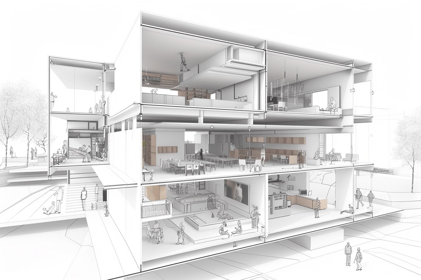



Table of Contents Show
An architectural sectional diagram is a drawing that shows a vertical cut through a building, revealing interior heights, floor levels, structure and spatial relationships that plans and elevations hide. It works like slicing through the structure to expose how its spaces stack and connect across every level.
Architects reach for this drawing whenever a plan or an elevation cannot answer a simple question: how do the spaces inside actually relate to each other vertically? A plan flattens the building into one horizontal layer, and an elevation only describes the outer face. A section cuts straight down, so you read ceiling heights, stair runs, structural depth and the way light travels between floors in a single view. That is why studios often draw the section early, while the design is still moving.
What Does a Sectional Diagram Actually Show?
The drawing answers one thing clearly: what happens inside the building from the ground up. Where the imaginary cut passes through floors, walls, the roof and the earth, those elements are drawn as solid, cut surfaces. Everything sitting behind the cut, such as a far wall, a staircase, built-in furniture or a window opening, is drawn in lighter lines so you can read depth without confusing it with structure.
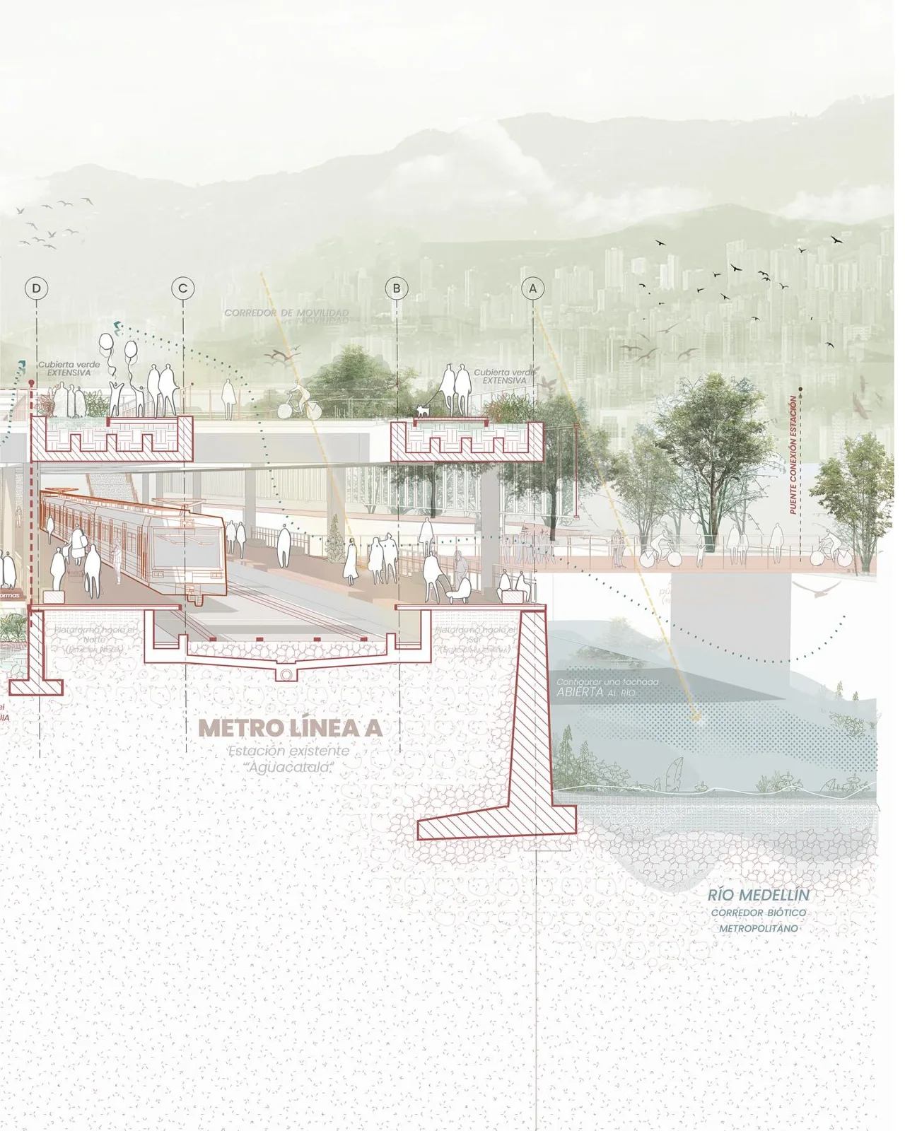
A section also carries the things a plan struggles to describe. Floor-to-floor heights, the thickness of a slab, the slope of a roof, a double-height void, the headroom under a stair, the depth a foundation reaches into the ground. Many sectional diagrams extend past the building itself to include the surrounding topography and neighbouring structures, which shows how the design meets its site rather than floating in isolation.
📐 Technical Note
Building sections are usually drawn at 1:50 or 1:100, while wall and detail sections move to 1:20, 1:10 or larger so material junctions resolve. The solid fill marking whatever the cut passes through is called poche, and by convention it carries the heaviest line weight in the drawing set.
Types of Sectional Diagrams
Not every section serves the same job. Architects switch between several kinds depending on what part of the building they need to explain, and recognising each one makes a drawing set far easier to read. The table below sets out the most common types, what each one reveals and when it earns its place in a set.

| Section type | What it shows | When to use it |
|---|---|---|
| Cross (transverse) section | Rooms stacked across the short axis, roof meeting the walls | Explaining how spaces relate vertically |
| Longitudinal section | Circulation, level changes and repeated spaces along the long axis | Reading sequence and flow through a building |
| Sectional perspective | The cut plus the three-dimensional depth of the space behind it | Concept presentation and conveying atmosphere |
| Exploded section | Components pulled apart along an axis to show assembly | Illustrating how parts of a structure fit together |
| Detail or wall section | A single junction from foundation to roof at large scale | Resolving construction layers and materials |
| Site or topographic section | The building together with ground, slope and context | Showing how a design sits on its landscape |
These categories overlap in practice. A single sheet might pair a 1:100 building section with a 1:10 detail of the same wall, so the reader moves from the whole structure down to a window head without losing the thread. For a wider look at the family of orthographic views, the multiview projection system places sections alongside plans and elevations.
📌 Did You Know?
In 2016, LTL Architects published the Manual of Section, a book devoted entirely to the architectural section as a design tool. It argues that thinking through section, rather than only in plan, is one of the most overlooked skills in the profession (ArchDaily, 2016).
How Do You Read a Section?
Reading a section starts on the plan, not the section itself. Somewhere on the floor plan you will find a cut line with arrows and a pair of letters, such as A-A. The arrows tell you which direction the viewer is looking, and the matching letters label the drawing you then turn to. Once you know where the knife passed and which way it faces, the section becomes a straightforward vertical map.
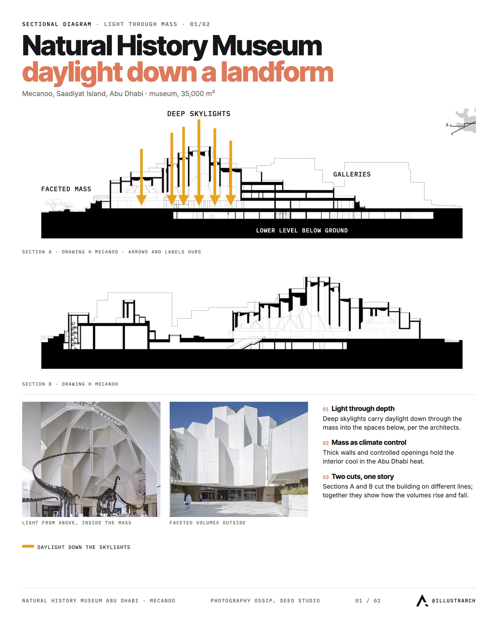
From there, line weight does most of the work. Whatever the cut slices through reads boldest, often filled solid as poche. Elements just beyond sit in medium lines, and distant background features fade to the lightest weight. Train your eye to read the heaviest lines first and a dense section becomes legible at a glance, because the difference between a structural wall and a piece of furniture is immediately obvious. Hatch patterns layered onto the cut surfaces signal materials, so concrete, masonry, insulation and earth each read differently.
🎓 Expert Insight
“A section is where a building stops being a picture and starts being a building. The moment you cut through it, you have to prove the stairs land, the ceilings clear and the structure actually carries.”
Licensed architect with 20+ years in practice
This is why many studios draw the section early. The cut exposes problems a plan can hide until a project reaches the site.
Annotations finish the reading. Level markers, key dimensions, a graphic scale bar and at least one human figure tell you how big the spaces truly are. Without that figure, a generous double-height hall and a cramped corridor can look identical on paper. If you want to study strong examples, this collection of successful architectural section drawings shows how practising architects handle depth and annotation.
Section, Plan and Elevation: Three Different Cuts
A section makes the most sense next to the two drawings it works with. A plan is a horizontal cut taken roughly a metre above the floor, looking down, so it describes layout, room sizes and the flow between spaces. An elevation is a straight-on view of an exterior face, describing the outside appearance, the windows, doors and finishes. Neither one tells you how tall a room is or how the floors connect.
The section fills that gap by cutting vertically and looking sideways. It exposes ceiling heights, the depth of structure, hidden services and the vertical relationship between levels that a plan and elevation leave out. The three drawings are not competitors, they are partners, and a design is only fully described when all three agree. ArchDaily makes this case well in its piece on the importance of the section in architectural representation, while Architizer offers a plain-language primer on what a section drawing is.
Why Sectional Diagrams Matter in Design
An architectural sectional diagram earns its keep from the first sketch to the last construction detail. Early on, it lets a designer test ideas that only exist in the vertical dimension, such as a sunken courtyard, a mezzanine, a stepped roof or daylight pulled deep into a plan. Problems that hide in a floor plan, a stair that runs out of headroom or a beam that clashes with a ceiling, show up the moment you draw the cut.
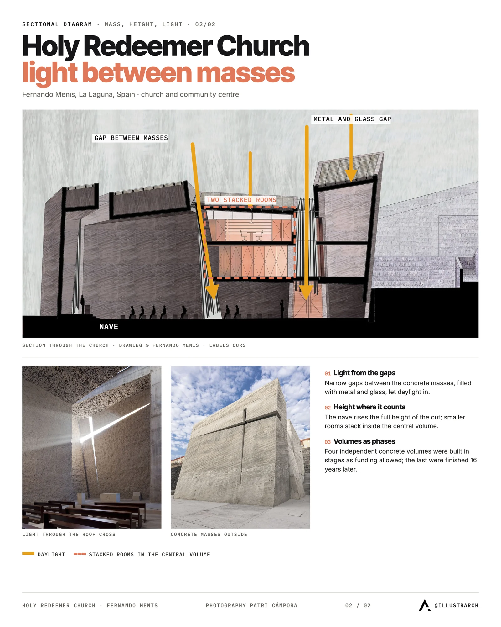
As a project develops, the same drawing becomes a contract for how things get built. Contractors read sections to understand slab thicknesses, insulation layers, waterproofing and the exact relationship between finishes. The clearer the section, the fewer surprises arrive on site. The drawing is also a shared language in client meetings and design reviews, translating spatial ideas into something everyone in the room can picture. To see how it fits the wider toolkit, it helps to compare it with related drawings used across the architectural design process and other visual tools such as massing diagrams. If you want to produce one yourself, this step-by-step guide to drawing an architectural section walks through the workflow.
The Bigger Picture
A plan tells you where things are and an elevation tells you what the building looks like, but only the section tells you what it feels like to move through it. That is the quiet reason architects keep returning to the cut: it is the one drawing that takes height, structure and human scale seriously at the same time. Learn to read poche, follow the cut line and look for the figure in the drawing, and an architectural sectional diagram stops being a technical puzzle and starts reading like a story of the space it describes.



3 Comments



Stacking Diagram: How to Allocate Uses Floor by Floor
A stacking diagram assigns each use in a brief to a level,...
 Sinan Ozen7 Mins read

Figure-Ground Diagram: How to Draw and Read Urban Fabric
A figure-ground diagram reduces a city to built mass against open space....
Sinan Ozen7 Mins read
Sun Path Diagram: How to Read One and Use It in Design
A sun path diagram shows where the sun sits all year for...
Sinan Ozen8 Mins read
Matrix Diagram in Architecture: How to Map Space Adjacencies
A matrix diagram, or adjacency matrix, maps how every space in a...
Sinan Ozen8 Mins read


This article explains sectional diagrams in architecture. It seems important for understanding how buildings are designed. I didn’t know they show both inside and outside details.
I really liked this article! It explains how sectional diagrams work in architecture so well. They help us see the inside of buildings, which is super cool! Now I understand why they’re important for architects. Great job!
This article explains how sectional diagrams help architects understand buildings better. They show how different parts of a building fit together and relate to the outside area. Sectional diagrams are important because they make complex designs easier to see and understand. I learned that these diagrams are used from the beginning of a project all the way to construction.