

Architectural Detail Drawings: What They Are and How to Create Them
A practical guide to architectural detail drawings covering their purpose in construction documentation, the main types (wall sections, joinery, waterproofing, and more), standard scales and line weights, software tools for creating them, and a step-by-step process for producing clear, buildable details from scratch.

Table of Contents Show
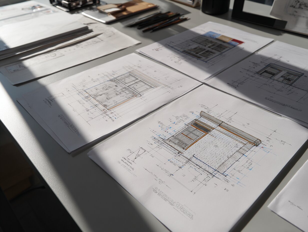
An architectural detail drawing is a large-scale drawing that shows how building components connect, what materials are specified, and how assemblies are constructed at a specific location within a project. These detailed drawings architecture professionals produce are the link between a design concept and what actually gets built on site, capturing dimensions, material layers, fasteners, and tolerances that general arrangement drawings cannot show.
What Is an Architectural Detail Drawing?

Architectural detail drawings are close-up views of construction assemblies drawn at scales large enough to show every material layer, connection method, and dimensional relationship. Where a floor plan or section might show a wall as a single line or a hatched band, the detail drawing zooms into that wall and reveals the stud spacing, sheathing type, vapor barrier position, insulation thickness, exterior cladding attachment, and interior finish. The purpose is to remove ambiguity so that the contractor can build exactly what the architect intended.
A single set of construction documents for a mid-size commercial project can include 50 to 200 individual architecture detail drawings. They appear on dedicated detail sheets (typically the A5xx or A7xx series in a standard AIA sheet numbering system) and are referenced from plans, sections, and elevations through detail markers, small circles containing a detail number and sheet number that tell the reader where to find more information.
Detail drawings in architecture differ from diagrams or sketches because they carry contractual weight. Once issued for construction, they become part of the legal documentation that defines the scope of work. Errors in a detail drawing can lead to rework, claims, and delays, which is why accuracy at this scale matters more than at any other drawing scale in the set.
💡 Pro Tip
Before drawing any detail, visit the site and photograph the actual conditions at that location. A detail drawn from the model alone often misses field realities like existing piping runs, uneven substrates, or tolerances that only become visible during construction. Experienced architects keep a running photo log linked to each detail number throughout the project.
Why Architectural Details Matter in Construction

Every building fails at its joints. Water gets in where the roof meets the wall, where a window sits in an opening, or where a foundation transitions to a slab. Architectural drawing details exist to address exactly these vulnerable points. A well-drawn detail anticipates water paths, thermal bridges, structural loads, movement joints, and material incompatibilities before they become problems on site.
Beyond waterproofing and structure, detail drawings serve as coordination tools. When the architect draws a parapet detail, the structural engineer checks that the steel angle supports the coping, the mechanical engineer confirms that the roof drain can fit within the assembly, and the envelope consultant verifies the air barrier continuity. Without that drawn detail, each discipline works from assumptions, and assumptions lead to clashes.
Contractors also use architectural details drawings to price work accurately. A general note saying “provide flashing at all window heads” leaves the estimator guessing at material quantities, labor time, and sequencing. A drawn detail showing the exact flashing profile, its integration with the weather-resistive barrier, and the sealant joint dimensions gives the estimator a concrete basis for a line item. This reduces bid uncertainty and, in most cases, lowers the contingency a contractor adds to their price.
🎓 Expert Insight
“God is in the details.” — Ludwig Mies van der Rohe
Mies van der Rohe’s famous statement reflects a principle that still holds in practice: the quality of a building is ultimately determined not by its massing or concept but by how precisely its parts come together. A beautiful facade design fails if the mullion detail leaks or the stone panel cracks at its anchor point.
Types of Architectural Detail Drawings
Detail drawings fall into several categories based on what part of the building they address and what information they convey. Understanding these types helps architects organize their detail sheets logically and ensures no critical condition is left undocumented.
Wall Section Details
Wall section details are among the most common detailed architectural drawings in any set. They show a vertical cut through the exterior wall assembly, revealing every layer from the interior finish to the exterior cladding. A typical wall section detail includes the stud or masonry backup, insulation type and thickness, vapor and air barriers, sheathing, drainage cavity (if applicable), cladding attachment system, and interior finishes. These details are usually drawn at 1:5 or 1:10 scale and often span from the foundation or floor slab to the roof parapet or eave.
Window and Door Details
Window and door details show the head (top), jamb (side), and sill (bottom) conditions for each opening type. They illustrate how the frame sits within the rough opening, where the flashing goes, how the sealant joints are configured, and how the interior trim finishes the transition. For curtain wall systems, these details become significantly more complex, showing thermal breaks, pressure plates, gaskets, and structural silicone joints.
Roof Details
Roof details cover conditions like eave edges, parapet caps, penetrations (pipes, ducts, equipment curbs), expansion joints, and transitions between different roofing systems. Since roof failures are among the most common and costly building defects, these details receive extra scrutiny during plan review and construction observation.
Foundation and Slab Details
These architecture detail drawings show the interface between the building and the ground. They include footing configurations, waterproofing membranes, drainage boards, slab-on-grade edge conditions, and control joint layouts. In regions with high water tables or seismic activity, foundation details become critical coordination documents between the architect and structural engineer.
Interior Finish Details
Interior details cover base conditions, ceiling transitions, custom millwork profiles, tile layout patterns, and specialty installations like acoustic panels or feature walls. These details often appear on interior elevation sheets rather than the main architectural detail sheets, but they follow the same drafting conventions.
Comparison of Architectural Detail Drawing Types
The following table summarizes how each detail type functions within a drawing set:
| Detail Type | Typical Scale | Primary Purpose | Key Information Shown |
|---|---|---|---|
| Wall Section | 1:5 or 1:10 | Envelope assembly | Material layers, insulation, barriers, cladding |
| Window / Door | 1:2 or 1:5 | Opening conditions | Flashing, sealant, frame profile, hardware |
| Roof | 1:5 or 1:10 | Weather protection | Membrane laps, edge profiles, penetrations |
| Foundation | 1:10 or 1:20 | Ground interface | Waterproofing, footings, drainage, slab edges |
| Interior Finish | 1:2 or 1:5 | Fit-out precision | Trim profiles, base conditions, millwork joints |
| Stair / Railing | 1:5 or 1:10 | Safety and code compliance | Nosing profiles, guard heights, handrail grips |
📐 Technical Note
Standard line weights for detail drawings follow ISO 128 conventions: cut elements use 0.5 mm or 0.7 mm lines, elements in projection (beyond the cut plane) use 0.25 mm or 0.35 mm lines, and hidden elements use dashed lines at 0.18 mm. In imperial practice, the AIA CAD Layer Guidelines (AIA Document G202) recommend similar weight distinctions using pen assignments in CAD and BIM software.
How to Create an Architectural Detail Drawing: Step by Step

Creating a clear, buildable detail drawing architecture piece requires a structured process. Jumping straight into drafting without preparation leads to missed conditions and rework. The steps below follow the workflow that most experienced practitioners use, whether they are working by hand or in BIM software.
Step 1: Identify the Condition to Detail
Start by reviewing your plans, sections, and elevations to find every location where materials change, assemblies meet, or construction sequences need clarification. Mark these locations with detail markers on your general drawings. Common triggers include wall-to-roof junctions, window head and sill conditions, expansion joints, material transitions (such as brick to metal panel), waterproofing terminations, and any custom or non-standard condition.
Step 2: Research Materials and Standards
Before drawing, gather the manufacturer’s installation details for the products you are specifying. Roofing membrane manufacturers, for example, publish CAD-ready details showing their required lap widths, adhesive patterns, and flashing configurations. Cross-reference these with applicable building codes (such as the International Building Code) and industry standards from organizations like ASTM International or the National Roofing Contractors Association.
Step 3: Choose the Right Scale
The scale of your detail depends on how much information needs to be visible. For general assembly details showing multiple layers, 1:10 (or 1″ = 1′-0″ in imperial) works well. For complex connections where every millimeter matters, move to 1:5 or even 1:2. Full-size details (1:1) are sometimes necessary for custom profiles like stone moldings, handrail grips, or specialty glazing gaskets.
Step 4: Draft the Detail
Begin with the structural elements (concrete, steel, or wood framing), then layer in the secondary components (sheathing, insulation, barriers), and finish with the visible surfaces (cladding, trim, finishes). Use consistent material hatches so that concrete is always the same pattern, insulation is always shown the same way, and so on. Add dimensions that the contractor actually needs: material thicknesses, clear distances, fastener spacing, and edge distances. Avoid over-dimensioning, which clutters the drawing and makes it harder to read.
Step 5: Annotate and Reference
Add keynotes or material tags that link to your specifications. A keynote system (using a numbered list that corresponds to specification sections) keeps the detail clean and reduces the chance of conflicts between the drawing and the written specifications. Include reference markers pointing to adjacent details, related sections, and any shop drawing submittals that will provide additional information.
Step 6: Coordinate with Consultants
Share your details with the structural and MEP engineers for review. Structural engineers will check connections, bearing conditions, and load paths. MEP engineers will verify that their pipes, ducts, and conduits can fit within the assemblies you have drawn. In a BIM workflow, this coordination happens through model-based clash detection, but the 2D detail still needs to reflect the resolved conditions. For teams using Autodesk Revit, details can be generated from the model and then enhanced with 2D linework and annotation in the detail view.
⚠️ Common Mistake to Avoid
A frequent error is labeling a detail as “typical” when the conditions it represents actually vary across the building. For example, a “typical window sill detail” may not account for differences in wall thickness, insulation type, or structural backup at different facades. If conditions differ, draw separate details for each variation rather than relying on field interpretation.
Scales and Line Weights for Detail Drawings

Scale selection directly affects how much information a detail can carry. Too small a scale compresses layers into unreadable slivers. Too large a scale wastes sheet space and forces the reader to assemble a mental picture from scattered fragments.
For most architectural details drawing work, architects stick to three primary scales. Assembly details that show how multiple components come together use 1:10. Component details that focus on a single connection or joint use 1:5. Profile details for custom shapes, gaskets, or ornamental elements use 1:2 or 1:1.
Line weight hierarchy is just as important as scale. The heaviest lines represent cut elements, the things the imaginary cutting plane passes through. Medium lines show elements in projection, visible beyond the cut plane. Light lines indicate hidden elements, dimension lines, and leaders. Consistent line weights across all details in a set help the reader quickly distinguish structure from finish, cut from projection, and existing from new.
When working in AutoCAD, line weights are typically controlled through layer assignments and plot style tables. In Revit, line weights are managed through the Object Styles dialog and can be further refined per view using Visibility/Graphics overrides. Both methods achieve the same goal: a clear visual hierarchy that makes the detail readable at a glance. For a deeper comparison of these two tools, see this comparison of AutoCAD and Revit workflows.
Software Tools for Creating Detailed Architectural Drawings
The choice of software affects how quickly and accurately you can produce architectural detail drawings. Each platform has strengths that suit different stages of the detailing process.
AutoCAD
AutoCAD remains the most widely used tool for 2D detail drafting. Its layering system, block libraries, and plot style tables give architects precise control over line weights, hatches, and annotation. Many firms maintain libraries of standard details in AutoCAD format that can be adapted for new projects, reducing drafting time significantly. The DWG file format is nearly universal in the construction industry, which makes sharing details with consultants and contractors straightforward.
Revit (BIM-Based Detailing)
Revit generates details from the 3D model, giving architects a head start by automatically cutting through modeled assemblies. The architect then adds 2D detail components (insulation fills, flashing lines, sealant beads) and annotations to complete the drawing. The advantage is that model changes automatically update the detail’s background geometry. The limitation is that Revit’s 2D drafting tools are less flexible than AutoCAD’s, so hybrid workflows (model-generated background plus CAD-drafted embellishments) are common. For an overview of how BIM and CAD tools fit into modern practice, this guide to BIM vs CAD workflows covers the practical trade-offs.
ArchiCAD and Other BIM Platforms
ArchiCAD, Vectorworks, and other BIM tools offer similar model-to-detail workflows. ArchiCAD’s detail tool allows architects to trace over model sections with independent 2D geometry, creating a live-linked detail that updates when the model changes but retains manually added annotations. Vectorworks provides a hybrid drawing environment that many design-led practices prefer for its graphic quality.
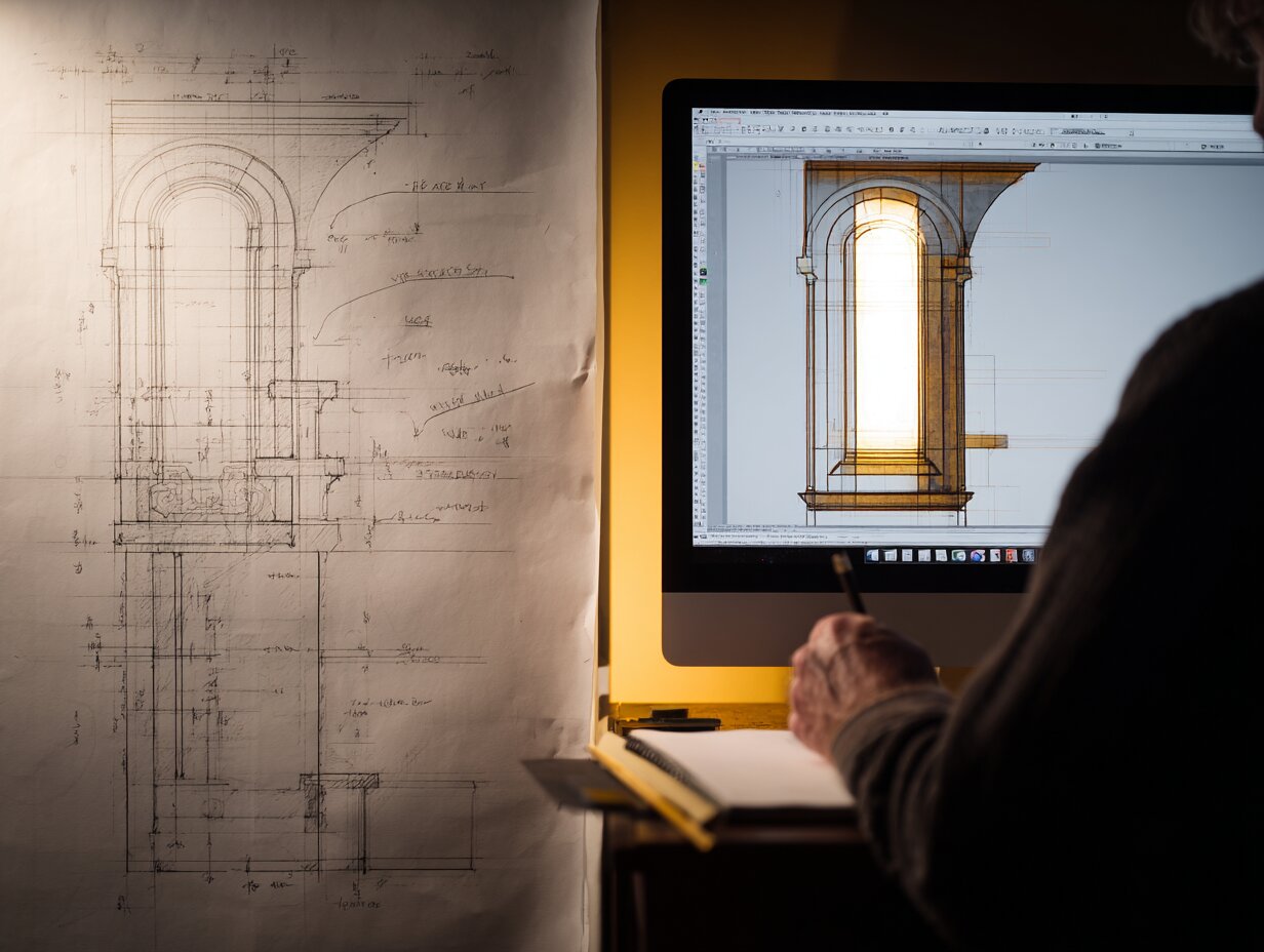
Hand Drafting
While rare in production work, hand-sketched details remain valuable during design development. Sketching a detail freehand forces the architect to think through every layer and connection without the distraction of software commands. Many senior architects still sketch details on trace paper during design meetings to test ideas before committing them to CAD. For guidance on improving freehand skills, this guide to architectural sketching for beginners covers fundamentals that apply to detail sketching as well.
💡 Pro Tip
Build a personal library of reusable detail components (insulation fills, flashing profiles, sealant joints, anchor bolts) in your primary CAD or BIM platform. A well-organized component library can cut detail drafting time by 30 to 50 percent on repeat project types. Update the library after every project based on lessons learned during construction administration.
How Architectural Detail Drawings Fit into Construction Documents
Detailed drawings architecture firms produce do not exist in isolation. They are part of a layered documentation system where each drawing type serves a specific communication purpose. Plans show horizontal layouts. Elevations show exterior faces. Sections reveal vertical relationships. Details zoom into specific conditions that the larger-scale drawings reference but cannot fully explain.
The referencing system works through a chain of markers. A floor plan contains section markers that point to building sections. Those building sections contain detail markers that point to specific detail drawings. The detail drawing itself may contain references to specification sections (through keynotes), related details on other sheets, and shop drawing submittals. This chain ensures that the reader can always trace from the big picture to the fine grain and back again. Understanding how these drawing types interrelate is foundational knowledge covered in our practical guide to reading construction drawings.
In a well-organized set, detail drawings are grouped by building system: exterior envelope details on one set of sheets, interior finish details on another, stair and railing details on a third. This organization helps contractors find what they need quickly and reduces the chance of missed information during bidding and construction.
🏗️ Real-World Example
The Shard (London, 2012): Renzo Piano Building Workshop produced over 12,000 individual detail drawings for this 310-meter skyscraper. The angled glass facade alone required hundreds of unique details to address varying angles, structural movement, wind loads, and thermal performance at different heights. Each floor plate’s relationship to the inclined curtain wall generated a distinct set of head, jamb, and sill conditions that could not be covered by a single “typical” detail.
What Makes a Good Architectural Detail Drawing?
Quality in detail drawing is not about artistic flair. It is about clarity, accuracy, and completeness. A good architectural detail drawing meets several criteria that separate professional-grade documentation from work that causes confusion on site.
First, every material layer must be clearly identified. The reader should be able to point to any line in the detail and know exactly what it represents. This is achieved through consistent hatching, clear keynotes, and a logical annotation hierarchy.
Second, dimensions should answer the questions a contractor will ask. How thick is the insulation? What is the air gap behind the cladding? How far does the flashing extend past the window frame? Where is the sealant joint, and what are its width and depth? If the contractor has to call the architect to ask about a dimension that should have been on the detail, the detail has failed its purpose.
Third, the detail must show the correct construction sequence. Materials are installed in a specific order, and the detail should make that sequence readable. Water management details, in particular, must show that each layer sheds water onto the layer below it, with no reverse laps or dead-end cavities where water could accumulate.
Fourth, the detail must be coordinated with the specifications. If the detail shows a specific sealant type, the specification section for sealants must include that product. Conflicts between drawings and specifications are one of the most common sources of construction claims. Using the same architectural drawing symbols and conventions throughout the set prevents misinterpretation.
📌 Did You Know?
According to a 2019 study published by the American Institute of Architects, approximately 40% of construction rework is attributed to incomplete or unclear documentation, with detail drawings being one of the most frequently cited sources of ambiguity. Improving detail quality at the documentation stage is one of the most cost-effective ways to reduce waste on site.
Common Elements in Every Architectural Detail Drawing

Regardless of type, certain graphic and informational elements appear in every professional architectural detail drawing. Understanding these components helps both the person producing the detail and the person reading it.
Material hatches follow industry conventions. Concrete is shown with a stipple pattern, earth with short diagonal lines, insulation with wavy or zigzag fills, wood with a grain pattern, and steel as a solid fill or diagonal hatches depending on the standard. These patterns are defined in standards like ISO 128 and the AIA Architectural Graphic Standards.
Keynotes or material tags link each element in the detail to a specification section. A numbered keynote system (for example, “03” for concrete, “07” for thermal and moisture protection, “08” for openings) aligns with the CSI MasterFormat organization used in most North American specification documents.
Dimensions include both overall dimensions (the total depth of a wall assembly, for instance) and component dimensions (each individual layer thickness). Reference dimensions connect the detail to control points established in the building sections, such as finish floor levels or structural grids.
Title blocks and detail markers identify each drawing with a unique number, a descriptive title, the scale, and a reference to the sheet where it appears. This identification system allows cross-referencing from plans, sections, and other details throughout the document set.
Video: Architectural Construction Drawings Process
This video walks through a typical set of detailed construction drawings, covering the process from initial layout to final documentation and showing how detail drawings fit within the full architectural drawing set.
Best Practices for Producing Detail Drawings
Producing architectural details drawings efficiently and accurately requires discipline beyond software skills. The following practices are drawn from standard professional workflows and reduce errors during both documentation and construction.
Standardize your detail library by building type. A firm that regularly designs healthcare facilities will develop a library of headwall details, clean room transitions, and radiation shielding assemblies that can be adapted project to project. Similarly, residential firms accumulate window installation details, porch framing details, and kitchen millwork sections. A standardized library saves time, but each detail must still be reviewed and adjusted for the specific project conditions.
Draw at the scale you intend to print. Drafting a detail at 1:5 and then printing it at 1:10 compresses the linework and makes annotations unreadable. If you know a detail will appear on a half-size sheet (which is standard for most field sets in North America), verify that your annotation sizes and leader spacing remain legible at that reduced scale.
Use consistent orientation across details. If your wall sections always show the exterior on the left and the interior on the right, maintain that convention for every wall detail in the set. Switching orientation between details forces the reader to reorient mentally, which slows reading and increases the chance of error.
Show tolerances and clearances explicitly. A detail that shows two materials touching with a perfectly clean joint does not reflect reality. Include construction tolerances (typically 3 mm to 6 mm for most assemblies), adjustment ranges for slotted connections, and clearances for tool access during installation. For more on how architectural plans and details work together in practice, this guide to creating architectural plans covers broader documentation strategies.
✅ Key Takeaways
- Architectural detail drawings are large-scale construction documents that show how building components connect, what materials are specified, and how assemblies are built at specific locations.
- The main types include wall sections, window and door details, roof details, foundation details, interior finish details, and stair and railing details, each drawn at scales appropriate to their complexity.
- Creating effective details follows a structured process: identify conditions, research materials and codes, choose scale, draft with correct line weights, annotate with keynotes, and coordinate with consultants.
- Quality detail drawings reduce construction rework, lower bid contingencies, and serve as legally binding contract documents that define the scope of work.
- Building a reusable detail component library and maintaining consistent graphic standards across a drawing set are two of the most effective ways to improve both speed and accuracy in practice.
Final Thoughts
Architectural detail drawings are where design intent meets physical reality. They are the most demanding drawings in a set to produce correctly, but they are also the drawings that have the greatest impact on how well a building performs over its lifetime. A roof that does not leak, a facade that does not crack, and a window that does not draft all depend on details that were drawn clearly, coordinated thoroughly, and built as shown.
For architects and students building their architectural drawing skills, investing time in learning detailing, both the technical knowledge of how materials behave and the graphic discipline of communicating that knowledge on paper, pays dividends in every project that follows. The detail is not a secondary part of the design process. It is where architecture becomes real.
Technical specifications and building code requirements referenced in this article vary by jurisdiction and project type. Always verify applicable codes and manufacturer installation requirements for your specific project with a licensed professional.
FAQ
What is the difference between an architectural detail drawing and a section drawing?
A section drawing shows a full vertical or horizontal cut through a building at a relatively small scale (typically 1:50 or 1:100), revealing overall spatial relationships, floor-to-floor heights, and structural systems. An architectural detail drawing zooms into a specific junction or assembly shown in that section, drawn at a much larger scale (1:5 or 1:10) to show material layers, fasteners, and dimensional relationships that the section cannot convey. Sections point to details through reference markers.
How many detail drawings does a typical project need?
The number depends on project complexity. A single-family residence might require 20 to 40 details. A mid-size commercial building typically needs 80 to 150. Large institutional or high-rise projects can exceed 200 individual detail drawings. The key is to draw a detail for every condition where materials change, assemblies intersect, or construction sequences require clarification.
What software is best for creating architectural detail drawings?
AutoCAD remains the most commonly used tool for 2D detail drafting due to its precise linework control and universal DWG compatibility. Revit is preferred in BIM workflows where details can be generated from the 3D model and annotated in place. Many firms use a combination of both: Revit for model-generated backgrounds and AutoCAD or Revit’s 2D tools for embellishment. The best choice depends on your firm’s workflow and the coordination requirements of your project.
What scales are used for architectural detail drawings?
The most common scales are 1:10 (or 1″ = 1′-0″) for assembly details, 1:5 (or 3″ = 1′-0″) for component details, and 1:2 or 1:1 for profile details. The scale should be large enough to clearly show all material layers and dimensions without cluttering the drawing. If a detail becomes too dense at one scale, consider splitting it into sub-details at a larger scale.
How do I organize detail drawings within a construction document set?
Group details by building system on dedicated sheets: exterior envelope details together, interior finish details together, stair and railing details together. Use a consistent sheet numbering system (such as A501, A502 for wall details and A601, A602 for interior details) and place detail reference markers on your plans and sections so that anyone reading the set can locate the relevant detail quickly.


MSI Titan 18 HX Review for Architects: Specs, Performance, and Limitations
A detailed MSI Titan 18 HX review through the lens of architectural...

Top 10 Architecture in the USA: Ranked by Revenue, Awards, and Specialty
A ranked breakdown of the top architecture firms in the USA covering...

Kingdom Centre Tower: Riyadh’s Inverted Parabolic Arch and Sky Bridge Explained
A detailed look at Kingdom Centre Tower in Riyadh, Saudi Arabia, covering...

Architecture Precedent Study: How to Analyze a Building Step by Step
Learn how to conduct an architecture precedent study with a structured, step-by-step...

Leave a comment