

Exploded Diagram Architecture: What It Is and How to Draw One
An exploded diagram in architecture lifts a building into its real assembly order so structure, skin, space, and services each read on their own. Learn what an exploded axonometric shows and how to draw one.
 Elif Ayse Sen14 July 20266 Mins read272
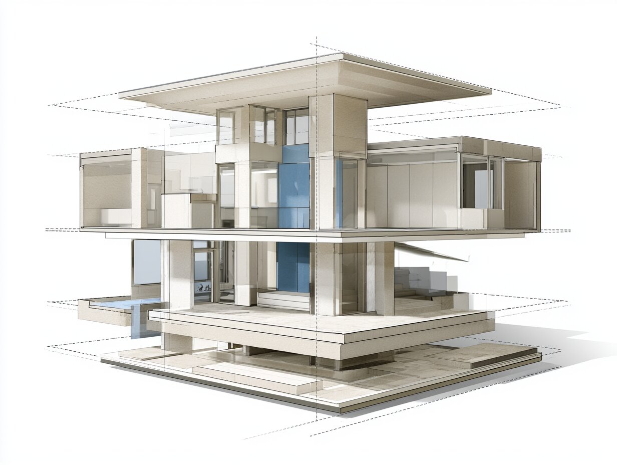
Table of Contents Show
An exploded diagram in architecture, often called an exploded axonometric, pulls a building apart into its separate layers so each system reads on its own. Exploded diagram architecture spaces structure, envelope, circulation, and services along a shared axis, showing both what the parts are and how they fit back together.
This drawing type sits between a technical instruction and a story. It borrows the logic of a parts catalog, where every component floats in its assembly order, and applies it to floors, walls, roofs, and frames. The result is a single image that explains a design faster than a stack of plans and sections ever could. The sections below cover what these diagrams are, how to read them, and how to draw one yourself.
What Is an Exploded Diagram in Architecture?
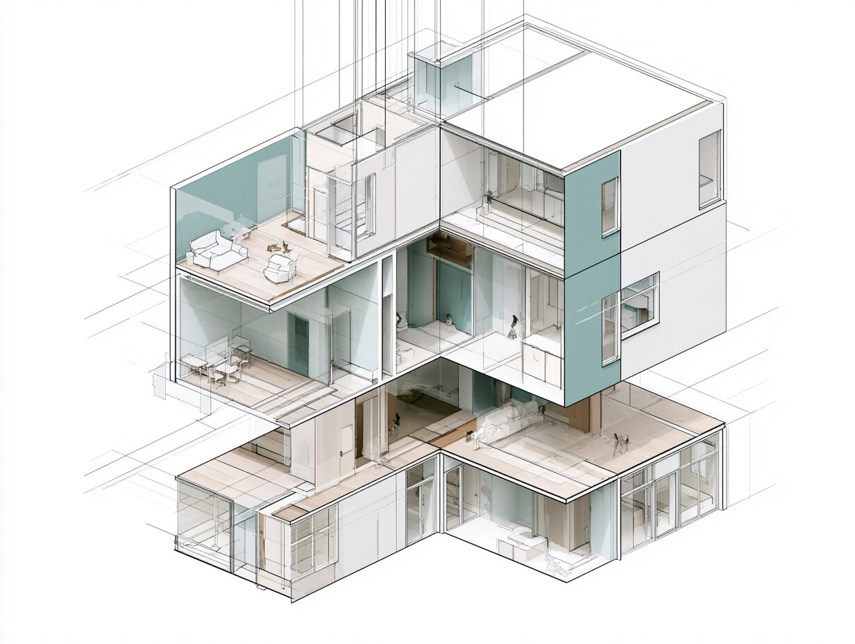
An exploded diagram in architecture is a drawing that separates a building into its individual parts and offsets them along one or more axes, so you can see how the pieces stack, slot, and connect. Nothing is removed. Every element keeps its real position relative to the others, just spaced out to expose the joints and layers that a finished view would hide.
The idea comes straight from engineering. An exploded-view drawing shows the parts of an object as if a small, controlled blast pushed them apart an equal distance from their assembled spots. Architects took that same convention and scaled it up from a gearbox to a whole building. In an architecture exploded diagram, the parts become the structural frame, the cladding, the floor plates, the roof, and the service runs.
🎓 Expert Insight
“An exploded view forces you to be honest about how a building actually goes together. If the layers do not line up cleanly in the drawing, that is usually a sign the detail does not resolve in real life either,” says a licensed architect with over 15 years in practice.
That observation matches a common studio experience, where the act of separating components surfaces coordination problems long before construction does.
Because the parts stay aligned to a single set of axes, an exploded diagram doubles as a coordination check. Designers use it to spot where a beam clashes with a duct, where a facade panel has nowhere to land, or where a stair meets the wrong slab. It communicates intent to a client and tests buildability for the team at the same time.
What Is an Exploded Axonometric?
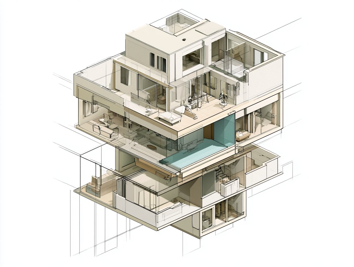
An exploded axonometric is the most common form of exploded diagram architecture, built on a parallel projection rather than a perspective view. In an axonometric, lines that are parallel in the building stay parallel on the page, and measurements hold true along each axis. That makes it the natural base for an exploded drawing, because separated parts can shift along clean vertical or horizontal lines without the distortion a perspective would add.
Axonometric is a family, not a single setting. The three standard types are isometric, dimetric, and trimetric, which differ by the angles between the axes. You can read the full breakdown in this guide to architectural axonometric diagrams, and the underlying math is covered in this look at the vector geometry behind these projections. When you stack the layers apart along the vertical axis, you get the classic exploded axon architecture diagram seen on competition boards.
📌 Did You Know?
Exploded-view drawing predates modern CAD by centuries. The technique appears in the notebooks of Renaissance engineers, including Mariano di Jacopo, known as Taccola, and Leonardo da Vinci, who pulled machine parts apart on paper to explain how they assembled long before any software existed.
The university tradition treats axonometric drawing as a core skill. The Carnegie Mellon teaching notes on axonometric projections set out the standard 30 and 45 degree constructions that most architects still draw by, and the formal definition lives in the entry on axonometric projection. Once those axes are fixed, exploding the model is a matter of sliding parts apart along them.
How Does an Exploded Diagram Differ from Other Drawings?
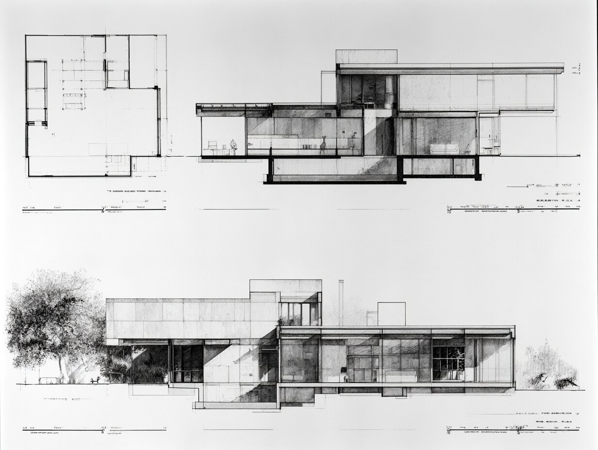
A plan, a section, and an elevation each cut or face a building from one direction and flatten it. An exploded diagram does the opposite. It keeps the whole object three-dimensional and instead separates it through depth, so you read the assembly order rather than a single slice. A section drawing tells you what a knife would reveal at one line, while a sectional diagram abstracts that cut into a concept. The exploded view sits apart from both.
The contrast also changes who the drawing is for. Plans and sections are working documents aimed at builders, dimensioned and coded for construction. An exploded diagram leans the other way, toward explanation, so a planning officer, a client, or a jury can grasp the design without reading a single dimension. Many studios produce both: precise construction sets for the contractor, and one clean exploded view that carries the idea in presentations. The two formats answer different questions, and a strong project usually needs each of them.
The table below sets the main exploded formats side by side so you can pick the right one for a given idea.
Exploded Diagram Types Compared
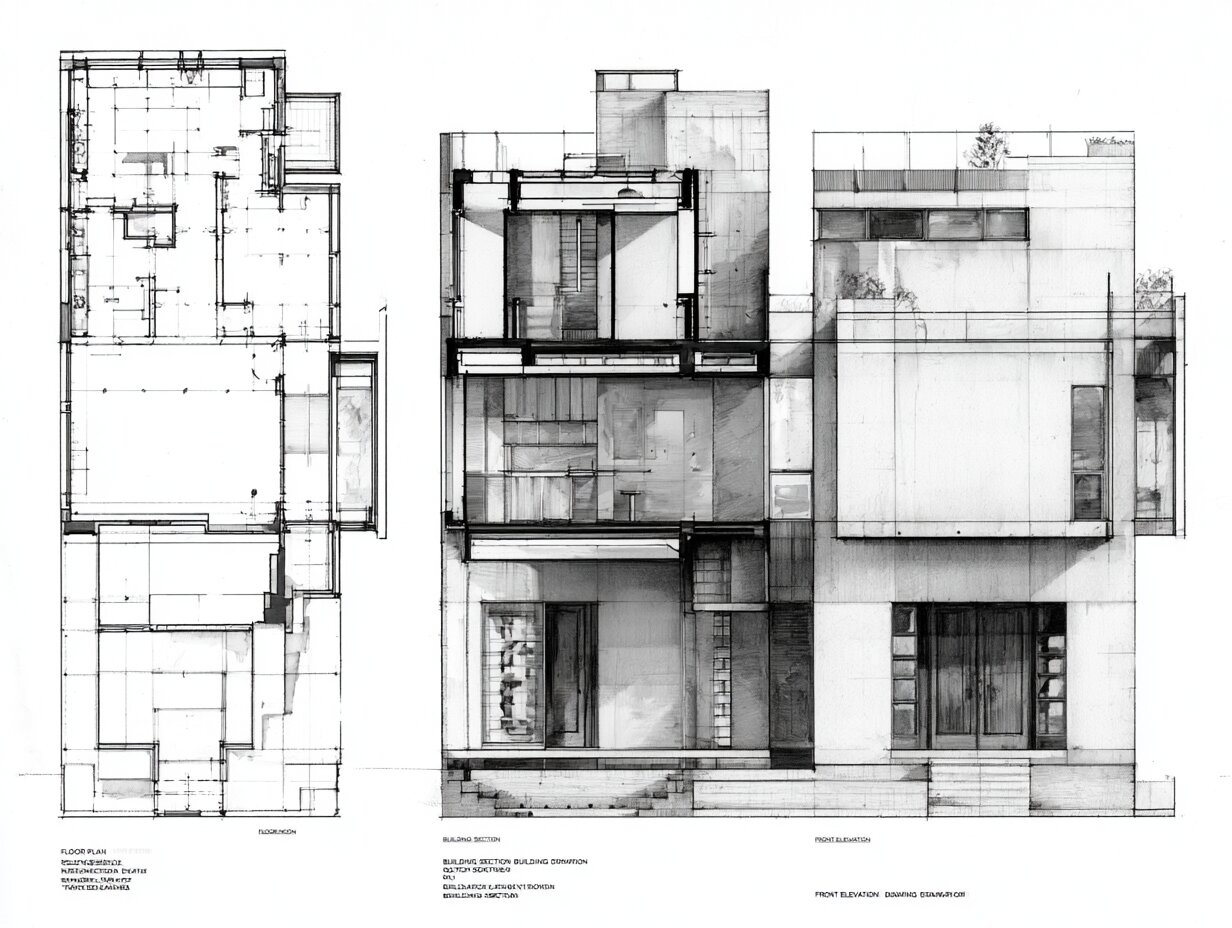
The following table summarizes how the common exploded formats differ in base projection and typical use.
| Diagram Type | Base Projection | What It Separates | Best For |
|---|---|---|---|
| Exploded axonometric | Parallel, true to scale | Floors, frame, envelope, services | Whole-building system logic |
| Exploded isometric | Equal 120 degree axes | Layers along one clean axis | Quick, measurable assembly views |
| Exploded column diagram | Vertical stacking | Repeated floor plates and cores | Towers and stacked programs |
| Exploded perspective | Converging lines | Parts within a scene | Marketing and atmospheric views |
The exploded column diagram architecture format deserves its own note. For a tower with many similar floors, you do not separate every part. You lift the typical floor plates apart vertically and pull the structural core to one side, which reads the repetition and the vertical circulation in one glance. For broader context on how these formats relate, this guide to architectural diagrams for students places the exploded view among its peers.
What Does an Exploded Diagram Reveal About a Building?
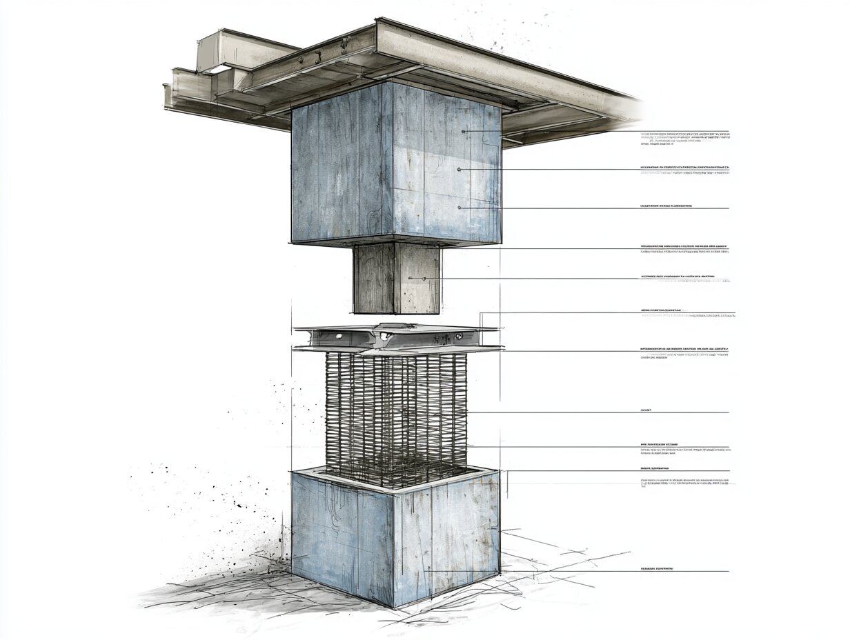
The value of an exploded view is layered reading. By separating systems, it answers questions that a solid model keeps hidden. You can see the structural grid on its own, then the facade that hangs off it, then the program inside, each as a distinct horizontal band in the drawing.
Designers usually break a building into four readable layers in an exploded architecture diagram: the load path, the enclosure, the occupied space, and the services. Keeping those bands consistent is what makes award-winning work legible, as in this set of strong architectural diagrams by practising architects. A reader with no technical training can follow a clear exploded axonometric, which is exactly why juries and clients respond to it.
🏗️ Real-World Example
CCTV Headquarters (Beijing, 2012): OMA relied on exploded axonometric diagrams to explain the building’s looping form, separating the structural diagrid, the floor plates, and the program zones along the vertical axis so a non-technical audience could follow how the unusual structure carried its loads.
That project shows the deeper point. An exploded diagram is not decoration added at the end. It is a thinking tool that makes a complex structural argument understandable, which is often the difference between winning a commission and losing one.
How to Make an Architecture Exploded Diagram

Knowing how to make an architecture exploded diagram comes down to a clear sequence, whether you draw it by hand or build it in software. The method stays the same: model clean parts, separate them along a single explosion axis, then guide the eye through the layers.
- Group your model into logical components first. Keep structure, envelope, floors, and services as separate groups so each can move on its own.
- Pick one explosion axis. Most building diagrams read best when parts rise straight up the vertical axis, which keeps the alignment obvious.
- Offset each layer by a consistent gap. Equal spacing reads as deliberate, while random gaps look like an accident.
- Keep every part directly above or below where it truly sits, so the reader can mentally drop the model back together.
- Add light leader lines or a faint ghost outline only if the assembly order is not already clear from position alone.
💡 Pro Tip
Explode along one axis only for your first draft. When parts scatter in two or three directions at once, the eye loses the assembly order and the drawing turns into a cloud of fragments. If a layer still reads as cluttered, cut detail before you add a second explosion direction.
Software handles the heavy lifting differently from one platform to another. Autodesk Inventor builds an explosion inside a dedicated presentation file, where you tweak each component along a vector, as its documentation on exploded views describes. In SketchUp the same effect is usually done by duplicating the model and moving each group apart by hand, then saving paired scenes to toggle between the assembled and exploded states. If you want a full diagram workflow rather than a single technique, this walkthrough on how to create architecture diagrams covers the production steps end to end.
Putting It All Together
Bottom Line: An exploded diagram architecture drawing takes a finished building, lifts it into its real assembly order, and lets structure, skin, space, and services each speak for themselves. Master the axonometric base, separate along one clean axis, and you hold a single image that explains a design and tests it at the same time.
- Architectural Diagram Concept
- Architectural Diagram Types
- Architectural Diagrams
- architecture exploded diagram
- Bubble Diagram
- Circulation Diagram
- exploded architecture diagram
- exploded axon architecture diagram
- exploded column diagram architecture
- exploded diagram architecture
- how to make architecture exploded diagram







Stacking Diagram: How to Allocate Uses Floor by Floor
A stacking diagram assigns each use in a brief to a level,...
 Sinan Ozen6 Mins read
Figure-Ground Diagram: How to Draw and Read Urban Fabric
A figure-ground diagram reduces a city to built mass against open space....
Sinan Ozen7 Mins read
Sun Path Diagram: How to Read One and Use It in Design
A sun path diagram shows where the sun sits all year for...
Sinan Ozen8 Mins read
Matrix Diagram in Architecture: How to Map Space Adjacencies
A matrix diagram, or adjacency matrix, maps how every space in a...
Sinan Ozen8 Mins read




Leave a comment