

What Is an Isometric Drawing in Architecture?
A clear look at isometric drawing in architecture, covering how the 120-degree projection works, how it compares to axonometric and perspective views, and how architects use it to communicate spatial relationships and layered building systems.
 Elif Ayse Sen15 July 20266 Mins read3

Table of Contents Show
Isometric drawing in architecture is a parallel projection that shows a building in three dimensions on a flat surface, with the three main axes set 120 degrees apart and drawn to a single consistent scale. Because the lines stay parallel rather than meeting at a vanishing point, you can measure directly off the drawing.
Architects reach for this method when they want a three-dimensional view that still behaves like a technical drawing. A floor plan tells you the layout, a section tells you the heights, and an isometric ties both together in one readable image without the distortion that comes with perspective. The trade-off is that an isometric never looks exactly the way the eye sees a real building, and that is the point.
What Is an Isometric Drawing in Architecture?
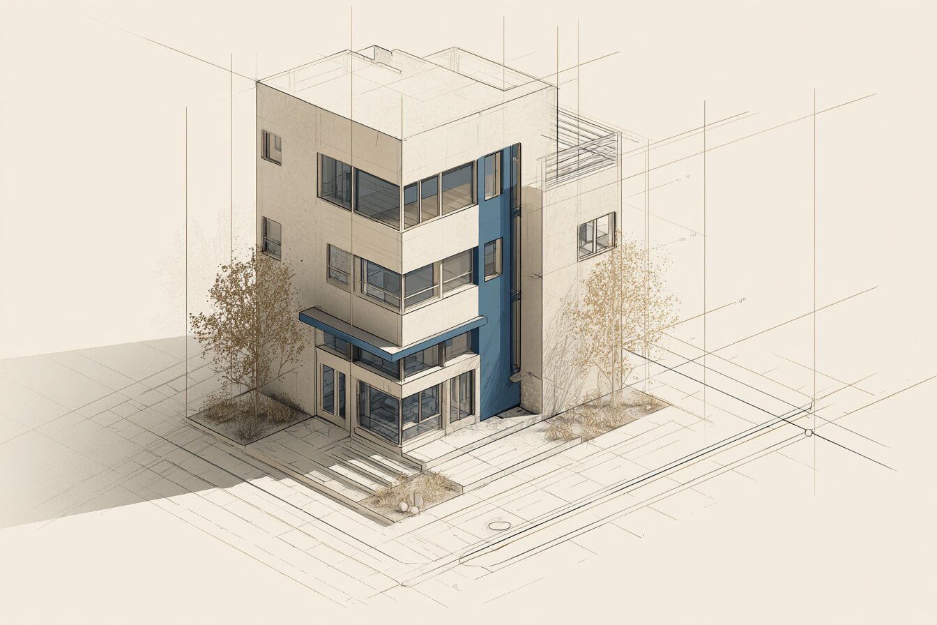
An isometric drawing is a type of axonometric projection where all three visible axes share the same scale and the same 120-degree spacing. The word isometric comes from Greek roots meaning equal measure, which describes exactly what happens: width, depth, and height are all drawn at the same ratio, so a one-meter line reads as one meter in every direction.
That equal treatment separates isometric drawing architecture from the perspective views used in renderings. In a perspective image, parallel edges converge and distant objects shrink. In an isometric, parallel edges stay parallel and nothing shrinks with distance. The result looks slightly flat or game-like, yet it carries reliable dimensional information, which is why it sits closer to plans and sections than to artistic renders. If you are mapping out how the different representation methods relate, the wider family of architectural diagrams gives useful context.
Two features define the method and explain why architects trust it. First, it is a parallel projection, so it has no vanishing point and no camera position to argue about. Second, it preserves true scale along each axis, which means a colleague can pick up a ruler and pull real numbers off the page. Those two properties make the isometric a bridge between the abstract precision of a plan and the spatial feel of a render, without fully committing to either.
How Does Isometric Projection Work?
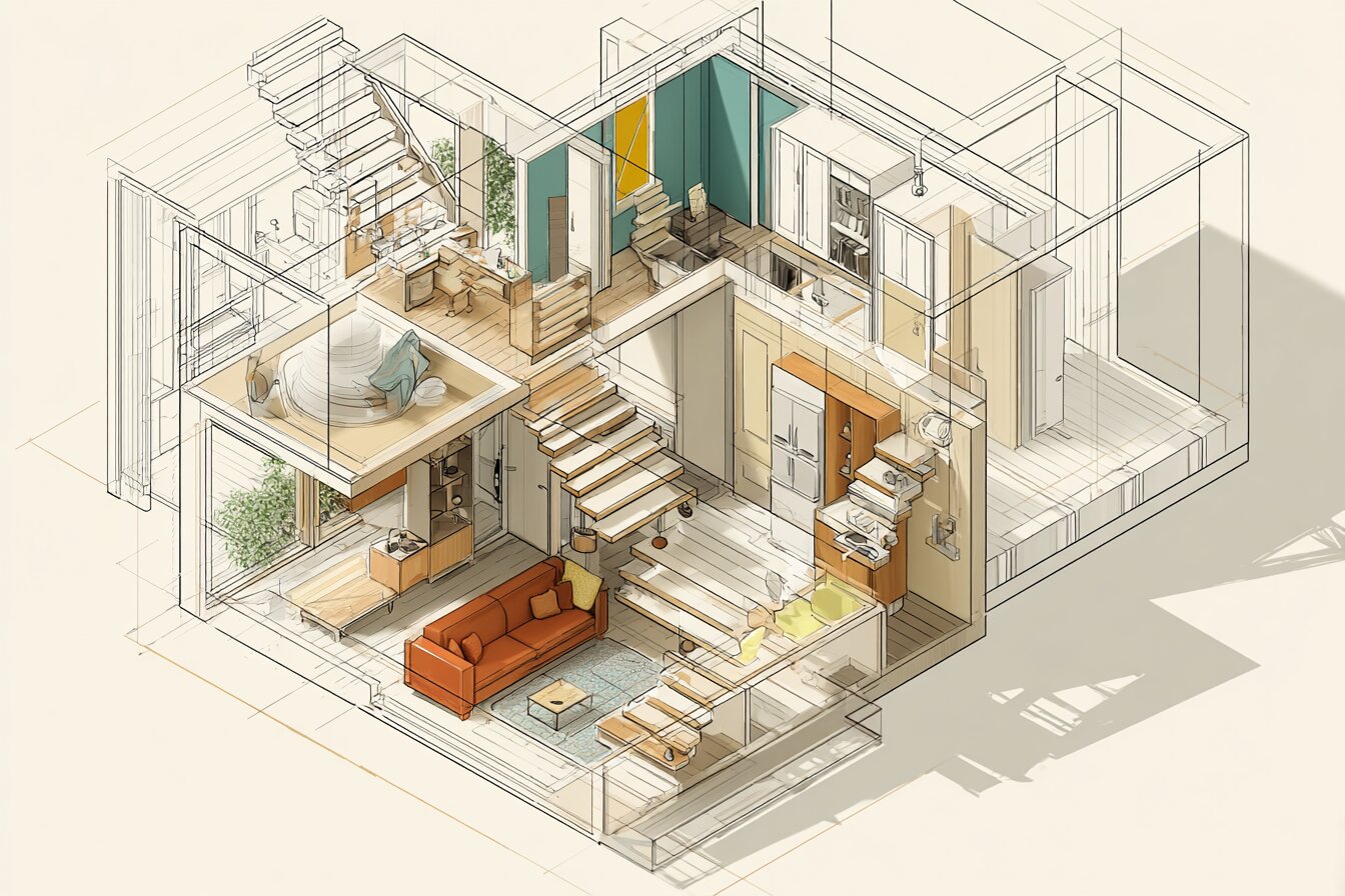
Isometric projection rotates an object so that no single face sits parallel to the viewing plane. Picture a cube tipped forward and turned until you see the top and two sides at once, with the vertical edges staying vertical and the two horizontal sets of edges running off at 30 degrees from the horizontal. Those two 30-degree lines plus the vertical give you the three axes, each separated by 120 degrees.
In true isometric projection, the geometry foreshortens every axis to about 81.6 percent of real length. Most architects skip that reduction and draw each axis at full scale, which technically produces an isometric drawing rather than a strict projection. The difference is invisible to the eye and saves a step, so the full-scale version became the working standard in practice.
📌 Did You Know?
The rules for isometric drawing were first set out by Professor William Farish of Cambridge University in his 1822 paper “On Isometric Perspective.” He wanted accurate working drawings that stayed free of the optical distortion built into single-point perspective, and his system spread quickly through engineering and architecture.
Once the axes are fixed, every measurement runs along one of them. Vertical heights climb the vertical axis, while plan dimensions split between the two 30-degree axes. Anything that does not align with an axis, such as a diagonal brace or a sloped roof, has to be plotted from its endpoints rather than measured straight off, since only axis-aligned lines keep their true length.
Isometric vs Axonometric vs Perspective
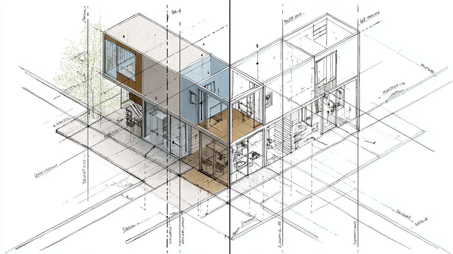
People often use isometric and axonometric as if they mean the same thing, but isometric is one member of the larger axonometric family. The table below sets the main three-dimensional methods side by side so you can see where each one fits and what it costs you in accuracy or realism.
Comparison of Common Architectural Projection Types
| Drawing type | Axis setup | Scale behavior | Best use |
|---|---|---|---|
| Isometric | Three axes at 120 degrees | Equal scale on all axes | Quick measurable 3D views |
| Dimetric | Two axes equal, one different | Two matching scales | Emphasizing one face |
| Trimetric | All three angles different | Three separate scales | Custom presentation angles |
| Planometric (plan oblique) | True plan rotated, verticals raised | Plan stays true scale | Reading floor layouts in 3D |
| Perspective | Lines converge to vanishing points | Objects shrink with distance | Realistic client renders |
| Orthographic (plan, section) | Single flat viewing plane | True scale, no depth shown | Construction documentation |
The practical takeaway is that isometric and its axonometric cousins keep measurements honest, while perspective trades that measurable accuracy for visual realism. For a deeper look at the parallel-projection side, this guide to the architectural axonometric diagram covers dimetric and trimetric variations in more depth. The flat measured views in the table relate directly to standard elevation drawings and to the section drawings architects pair with them.
💡 Pro Tip
A common slip is labeling a drawing isometric when it is actually planometric. If you rotated a true floor plan and pulled the walls straight up, you built a plan oblique, not an isometric. Check the base: an isometric has no true plan or elevation in it, since every face tilts away from the page.
Where Do Architects Use Isometric Drawings?
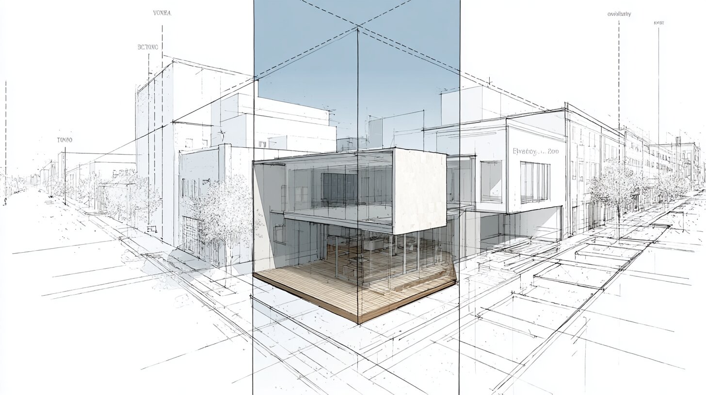
Isometric and axonometric views earn their place wherever a single image needs to explain how parts fit together. The most powerful version in architecture is the exploded isometric, which lifts a building apart along its axes so structure, envelope, circulation, and services each float as a separate layer. This makes the logic of a complex building readable at a glance, something a flat plan struggles to do on its own.
The method also suits the early stages of design, before any surface or material has been chosen. A rough isometric block model lets you test massing, check how floors stack, and study how light might reach a courtyard, all while the drawing stays measurable. Because the view holds true scale, you can hand it to an engineer or a planning officer and they read the same dimensions you intended, with no guesswork about foreshortening. That shared reliability is why the format survives in an age of photo-real rendering.
🏗️ Real-World Example
Centre Pompidou (Paris, 1977): Renzo Piano and Richard Rogers pushed the structure and mechanical services to the outside of the building. That inside-out design is almost always explained through exploded axonometric and isometric drawings, since pulling each system into its own layer is the clearest way to show how the parts stack and connect.
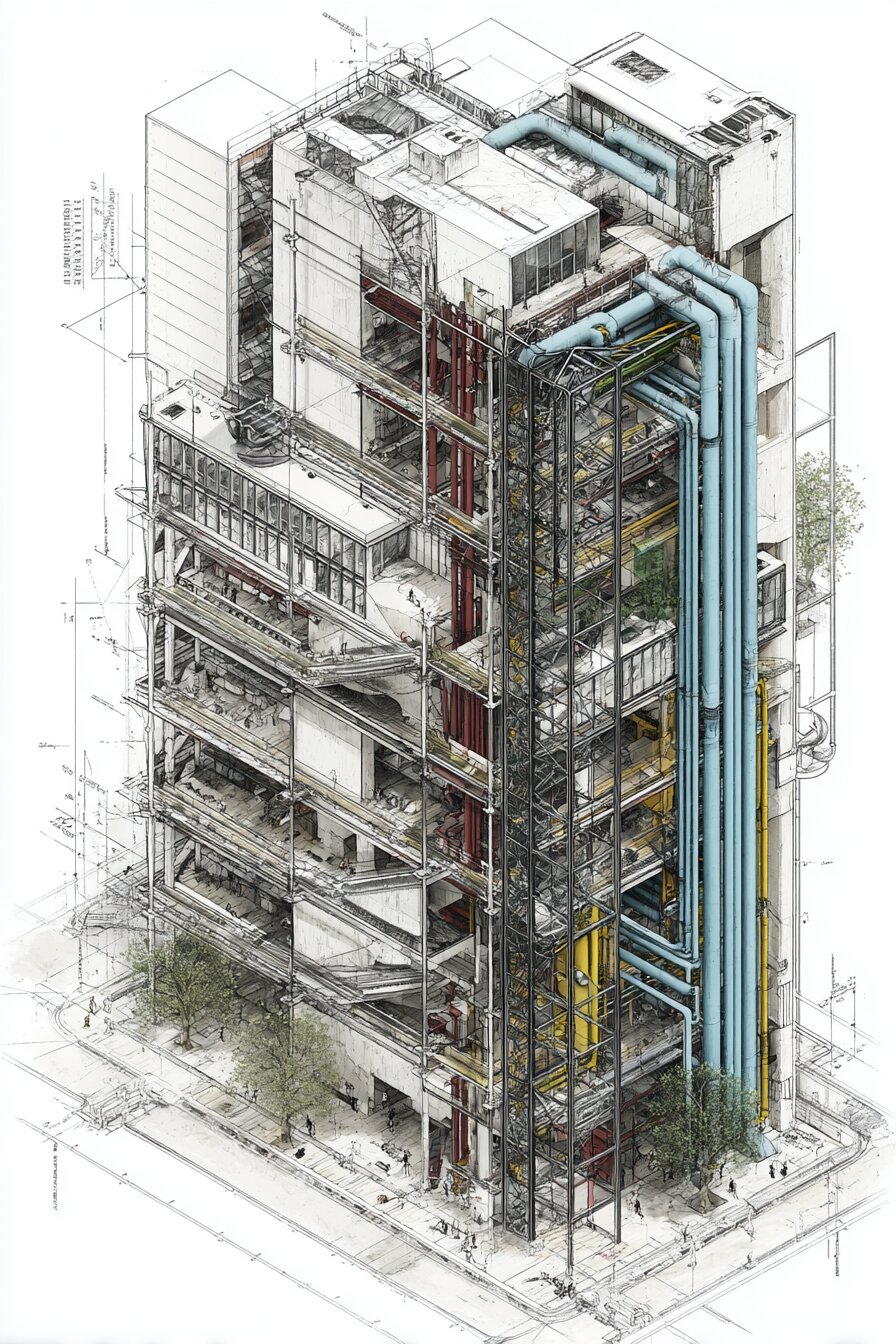
Beyond the exploded view, architects use isometric drawings for interior fit-outs, urban blocks seen from above, furniture and joinery details, and competition boards where one measured three-dimensional image can replace several flat drawings. The method also reads well at small sizes, which suits diagrams that sit alongside text. You can see the range of these uses in collections of architectural diagrams by practicing architects and in studies of structural diagrams that rely on the layered approach.
🎓 Expert Insight
“An axonometric forces you to decide what the building actually is, because you cannot hide a weak idea behind a flattering camera angle.”, Licensed architect with more than 20 years in practice
That observation captures why studios still draw measured projections by hand during early design. The honesty of equal scale exposes proportion problems that a polished render can quietly smooth over.
How to Draw an Isometric View

Setting up an isometric is mostly about discipline with the axes. Software such as AutoCAD includes a dedicated isometric drafting mode, and the official Autodesk help on 2D isometric drawing walks through the isoplane toggles. Whether you draw by hand or on screen, the underlying steps stay the same.
- Draw a vertical line for height, then two baselines running off at 30 degrees left and right.
- Measure real dimensions along each of these three axes, keeping the scale identical on all of them.
- Build the box that contains your object first, then subtract and add detail inside it.
- Plot any sloped or diagonal element from its two endpoints, never by measuring the slope directly.
- Keep circles as isometric ellipses, since a true circle distorts predictably on each isometric face.
For students moving from flat drawings into three dimensions, pairing this routine with a solid grounding in architectural drawing symbols keeps your isometrics consistent with the rest of a drawing set. University teaching resources, such as this City Tech open courseware lesson on architectural drawings, place isometric views within the full sequence of plans, sections, and elevations. The deeper geometry behind the method is set out in the reference on isometric projection.
Isometric drawing rewards practice more than talent. Once the 30-degree habit settles in, you start reading buildings as stacked boxes, and that mental model carries straight into how you sketch, model, and explain a design to other people. The measured three-dimensional view stays useful long after the first render is forgotten, because it answers the question every collaborator eventually asks: how does this thing actually go together?
- architect drawing tools
- Architectural Drawing
- architectural drawing basics
- Architectural Drawing Symbols
- architectural drawing techniques
- draw isometric drawing
- isometric drawing
- isometric drawing architecture
- isometric drawing examples
- isometric drawing tool
- isometric drawings
- isometric perspective drawing
- what is isometric drawing
- what is the isometric drawing




Exploded Diagram Architecture: What It Is and How to Draw One
An exploded diagram in architecture lifts a building into its real assembly...
Elif Ayse Sen6 Mins read
Bubble Diagram for Residential Projects: From Brief to Layout
A step-by-step look at how a bubble diagram organizes a residential brief...
Elif Ayse Sen8 Mins read
Spatial Organization Diagrams in Architecture: Types, Examples, and How to Choose
This guide breaks down the five core types of spatial organization diagrams...
 Sinan Ozen11 Mins read
Bubble Diagram School Design: A Step by Step Guide for Educational Buildings
A practical look at bubble diagram school design for educational buildings. It...
Elif Ayse Sen10 Mins read


Leave a comment