

Construction Documents Architecture: From Schematic to Working Drawings
A plain-language look at construction documents architecture, tracing the path from schematic design through design development to a fully detailed set of working drawings, specifications, and schedules.
 Elif Ayse Sen6 July 20266 Mins read236
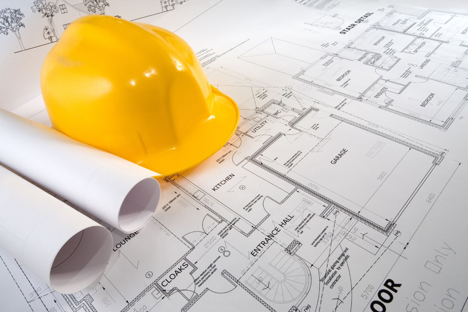
Table of Contents Show
Construction documents architecture firms produce are the drawings and written specifications that tell a contractor exactly what to build and how to build it. They mark the final design phase, turning approved schematic ideas into a precise, buildable set that covers dimensions, materials, assemblies, and the performance standards a project has to meet.
Getting from a loose first sketch to a signed, permit-ready set is a long road, and the documents change character at every step. A schematic plan exists to test an idea. A working drawing exists to build it without guesswork. Knowing how that shift happens helps you read any drawing set faster and catch coordination problems before they reach the field.
What Are Construction Documents in Architecture?

Construction documents are the final package of drawings and written specifications an architect prepares so a building can be priced, permitted, and built. The set has two halves that depend on each other: the graphic drawings that show size and location, and the specifications that define quality and materials. One half without the other leaves gaps a contractor will fill with assumptions.
The drawings carry geometry. They show where a wall sits, how thick it is, and how a stair connects two levels. The specifications carry standards. They name the grade of concrete, the performance class of a window, and the testing a finish has to pass. Both become legal instruments once a contract is signed, which is why precision here matters more than at any earlier stage of the architectural design process.
📌 Did You Know?
The American Institute of Architects organizes a standard project into five service phases, and construction documents is the largest of them by hours and output. On a mid-size commercial job, the CD set alone can run to several hundred sheets once structural, mechanical, electrical, and plumbing drawings are coordinated with the architectural sheets.
From Schematic Design to Working Drawings: The Five Phases

The American Institute of Architects splits a standard project into five service phases: schematic design, design development, construction documents, bidding or negotiation, and construction administration. Each phase sharpens the same design, adding resolution and removing ambiguity as the work moves toward the site. This layering is the backbone of construction documents architecture as a discipline, since the documents are not separate projects, they are the same building described at finer and finer grain.
The table below maps what each phase produces and why it exists.
Phase, Documents, and Purpose at a Glance
| Phase | Main Documents | Purpose |
|---|---|---|
| Schematic Design | Study plans, sections, massing, site plan | Test the concept and confirm program and scale |
| Design Development | Refined plans, wall types, system layouts | Resolve materials, structure, and major systems |
| Construction Documents | Working drawings, details, schedules, specifications | Define exactly what gets built and to what standard |
| Bidding or Negotiation | Bid set, addenda, instructions to bidders | Price the work and select a contractor |
| Construction Administration | Submittals, RFIs, field reports, revisions | Keep the built work true to the documents |
Schematic Design
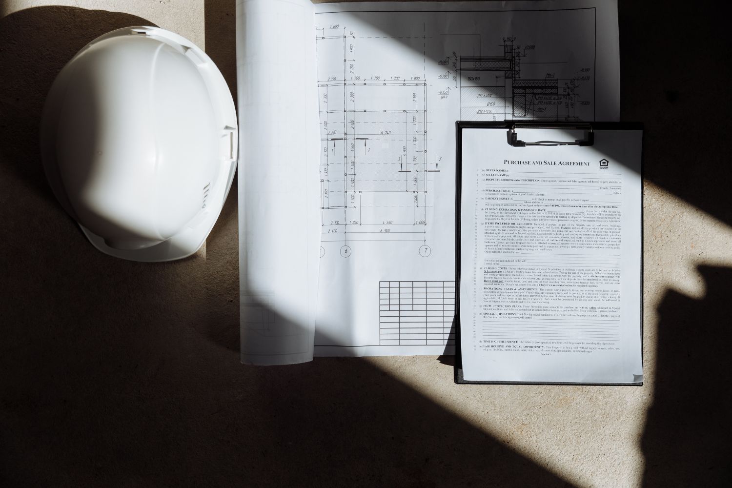
Schematic design is where the building first takes shape on paper. You produce loose floor plans, a few sections, simple massing, and a site plan, all aimed at testing whether the program fits and whether the form holds together. Dimensions are approximate. The goal is agreement on the idea, not buildable detail, so a schematic plan reads more like a diagram than a technical drawing.
Design Development
The design development stage takes the approved concept and resolves it. Walls get drawn to real thickness, a structural grid is set, room sizes are locked, and the engineering disciplines start coordinating their systems with the architecture. By the end of this phase the building is substantially defined, and most of the major material and system decisions are made. Everything that follows in the CD set builds on these choices.
Construction Documents and Working Drawings
The construction documents phase converts a resolved design into instructions a builder can follow line by line. This stage is the heart of construction documents architecture, where every earlier decision becomes a measurable, buildable instruction. This is where working drawings live: fully dimensioned plans, sections, elevations, large-scale details, and the schedules that track doors, windows, and finishes. The NCARB exam division on project development and documentation treats this assembly and coordination of a complete drawing set as a core competency for licensure, which signals how much of professional practice rides on getting it right.
💡 Pro Tip
Before you start drawing details, lock the wall types and the sheet list. When a detail references a wall assembly that changes later, every callout tied to it has to be hunted down and corrected. Settling the assemblies first saves hours of rework once the set grows past a few dozen sheets.
What Goes Into a Construction Document Set?
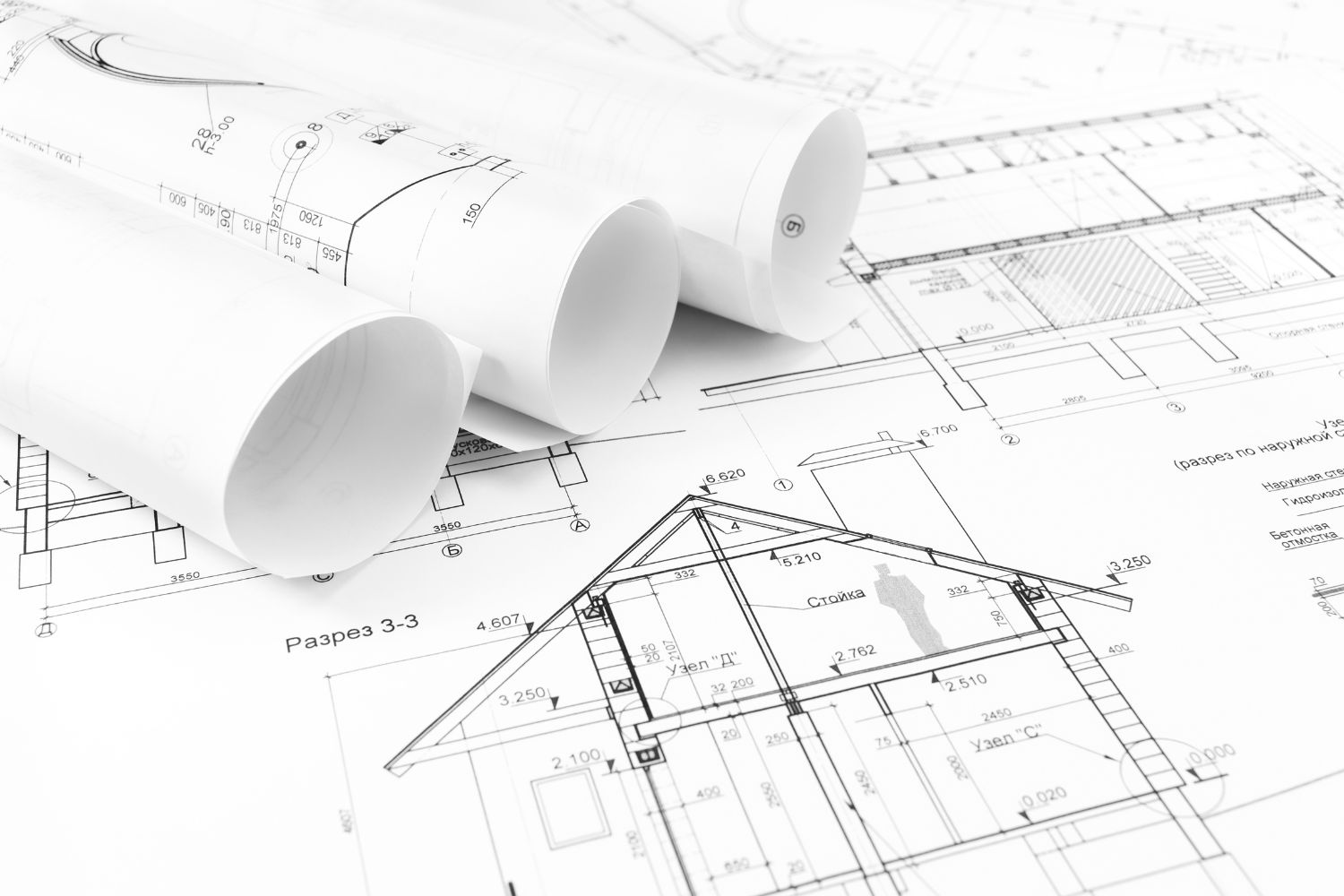
A finished construction documents architecture set is organized so anyone on the project can find a piece of information fast. The drawings are grouped by discipline, the specifications sit in a separate written volume, and schedules and details tie the two together. Here is how those parts work.
Drawings
Drawings are the graphic backbone of the set. Plans show horizontal cuts, elevations show exterior faces, and section drawings reveal the vertical relationships and how assemblies stack. Every sheet relies on a shared graphic language, so reading the architectural drawing symbols correctly is the difference between understanding a set and guessing at it. The conventions behind these documents are well summarized in the reference on architectural drawing, which traces how plans, sections, and elevations developed into the standard set used today.
Specifications
If the drawings answer where and how big, the specifications answer how good. They name products, reference performance standards such as ASTM or AAMA, and set the testing and tolerances a material has to satisfy. A drawing might call out a curtain wall, but the specification defines its thermal performance, its glazing, and its warranty. The written specification standard carries equal legal weight with the drawings, and university technical-literature guides such as the one from the University of Illinois architecture library point students toward the building codes and product standards that specs cite.
Schedules and Detail Drawings
Schedules are compact tables that track repeated elements, with door, window, hardware, and finish schedules among the most common. Instead of labeling every opening on the plan, you tag it and let the schedule carry the data. Detail drawings work the opposite way, zooming in to show exactly how parts meet. Learning to produce clear detail drawings is one of the most valued skills in a CD team, because a detail is where a design either becomes buildable or falls apart.
📐 Technical Note
Most North American specifications follow the CSI MasterFormat system, which sorts written sections into numbered divisions, from Division 03 for concrete to Division 26 for electrical. Pairing this consistent numbering with a logical sheet sequence lets a reviewer cross-reference a drawing callout to its spec section in seconds.
How Do Working Drawings Differ From Schematic Drawings?
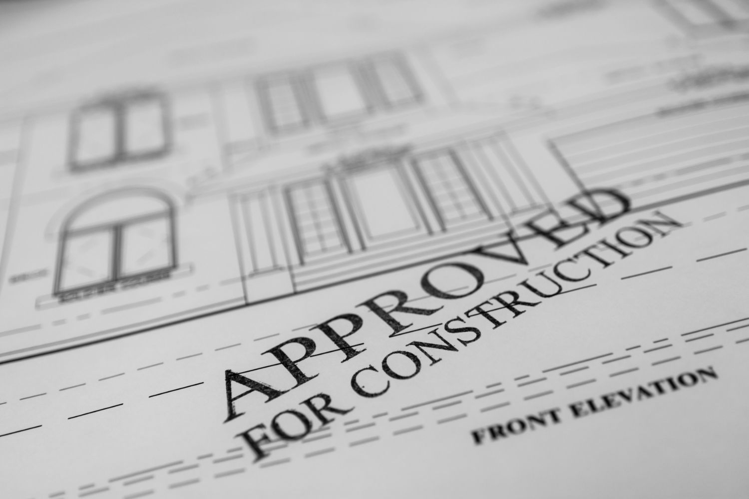
Working drawings differ from schematic drawings in one word: certainty. A schematic plan tests an idea with loose lines and round numbers, while a working drawing commits to exact dimensions, real materials, and the connections that let a crew build without interpreting intent. The same plan view exists in both, but the working version carries the data a contractor needs to order materials and price labor.
This is why a set grows so much in the final phase. A schematic floor plan might be a single sheet, while the working version of that floor splits into dimensioned plans, enlarged plans, reflected ceiling plans, and a stack of details. The intent never changed, but the resolution multiplied. If you want to see how that finished resolution reads in practice, this guide on how to read a construction drawing set walks through it sheet by sheet.
⚠️ Common Mistake to Avoid
A frequent error is treating the drawings and specifications as describing the same information twice. They do not. The drawings show quantity and location, the specs define quality and standards. Repeating a material spec on a drawing creates two sources of truth that drift apart during revisions, which leads to conflicting instructions on site. State each fact once, in the right document.
A Construction Documents Checklist for Architects
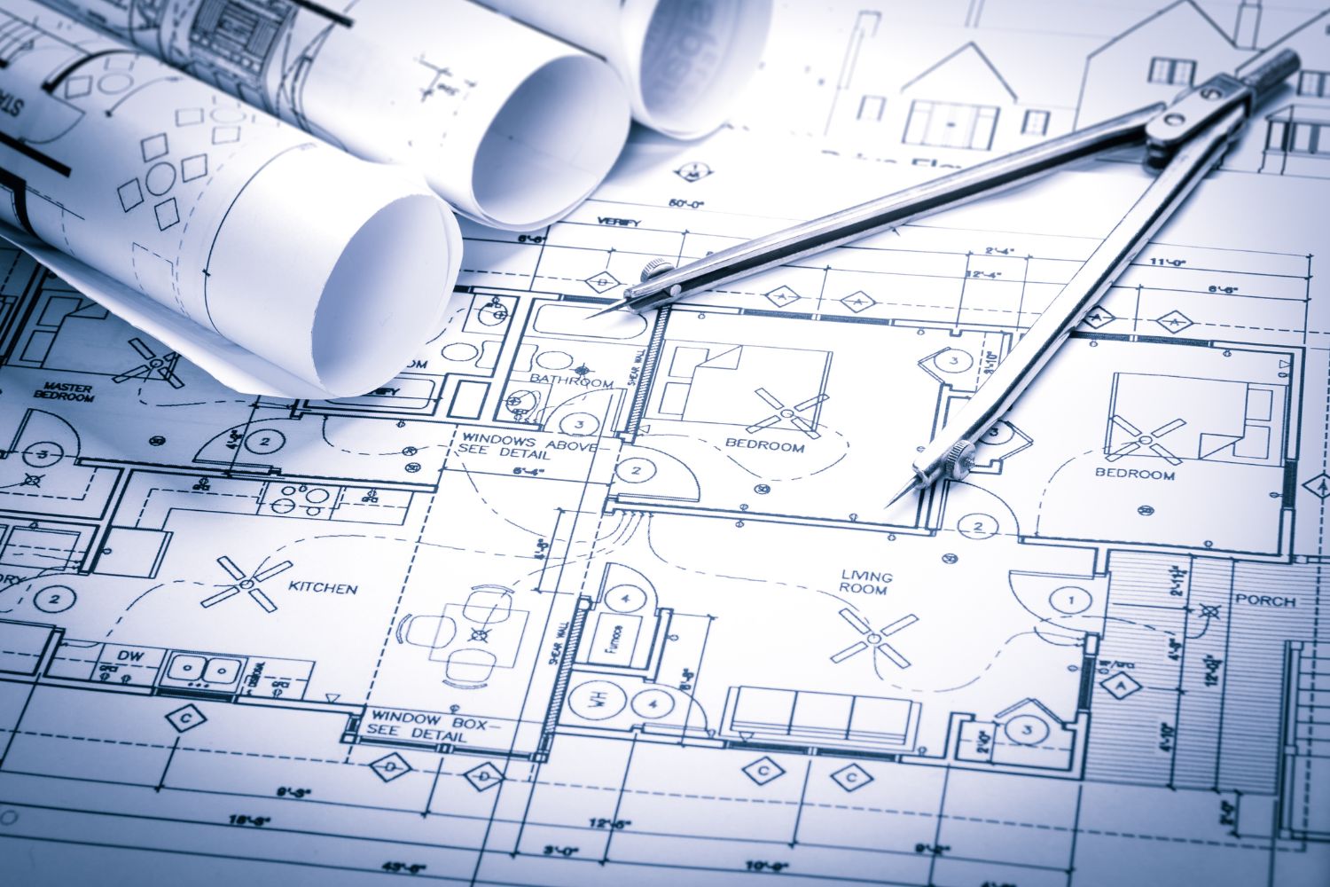
An architectural construction documents checklist keeps a large set honest as it grows. Use the points below as a coordination pass before any major issue or permit submission.
- Confirm the sheet list matches the actual sheets, with no gaps or orphaned numbers.
- Check that every detail callout points to a detail that exists and is current.
- Verify wall types on the plans match the wall-type legend and the details.
- Reconcile door, window, and finish schedules against the tagged plans.
- Coordinate structural, mechanical, electrical, and plumbing drawings against the architectural background.
- Confirm every drawing callout for a material has a matching specification section.
- Run a code and accessibility check against the life-safety and egress plans.
Catching these inside the office is far cheaper than catching them as a field question. A single unanswered conflict can stall a trade for days while everyone waits on a clarification.
Building codes and permitting requirements vary by jurisdiction. Always confirm the required document set with your local authority having jurisdiction before submitting for permit.
Where to Go From Here
Your Next Step: Pull a recent project set and run the seven-point checklist above on a single floor, starting with the sheet list and the detail callouts. That one pass will show you faster than any reading where your documents are tight and where a contractor would have to stop and ask.
- analyzing construction drawings
- architectural construction document checklist
- architectural construction documentation
- architectural construction documents
- architectural construction documents checklist
- architectural schematic drawings
- architecture construction documents
- construction documents architecture
- construction documents education
- construction drawings analysis
- landscape architecture construction documents
- what are construction documents in architecture
- what is construction documents in architecture








Architecture Beneath the Surface: The Crucial Role of Structural Mechanics and Geotechnical Analysis in Groundwork Design
Bold architecture depends on the ground beneath it. How numerical geotechnical analysis...
 illustrarch Editoral Team1 Mins read

Designing Renovation Projects Around Debris Flow and Site Logistics
Effective renovation planning must prioritize debris flow management. Learn how to integrate...
illustrarch Editoral Team4 Mins read

How Long Does a Building Warranty Typically Last? Coverage Periods Explained
Building warranty cover is layered, not uniform: one year for finishes, two...
 Sinan Ozen5 Mins read

What Is an Architect’s Certificate of Practical Completion?
A practical breakdown of the architect's certificate of practical completion: who issues...
Sinan Ozen6 Mins read


Leave a comment