

Architectural Drawings: A Student’s Guide to 8 Essential Types
A clear introduction to the eight architectural drawing types every student meets early: floor plans, elevations, sections, detail drawings, axonometric and perspective views, and concept sketches, plus what each one is used for.

Table of Contents Show

What Are Architectural Drawings?
An architectural drawing is a technical illustration that records a building’s form, dimensions, materials, and spatial relationships. Some are precise, measured documents used for permits and construction. Others are looser, conceptual studies meant to test an idea. Drawn with standard drawing symbols and consistent scales, these architectural drawings become a shared language that architects, engineers, and contractors all read the same way. University references like The New School’s architecture drawing guide point to the textbooks that codify these conventions.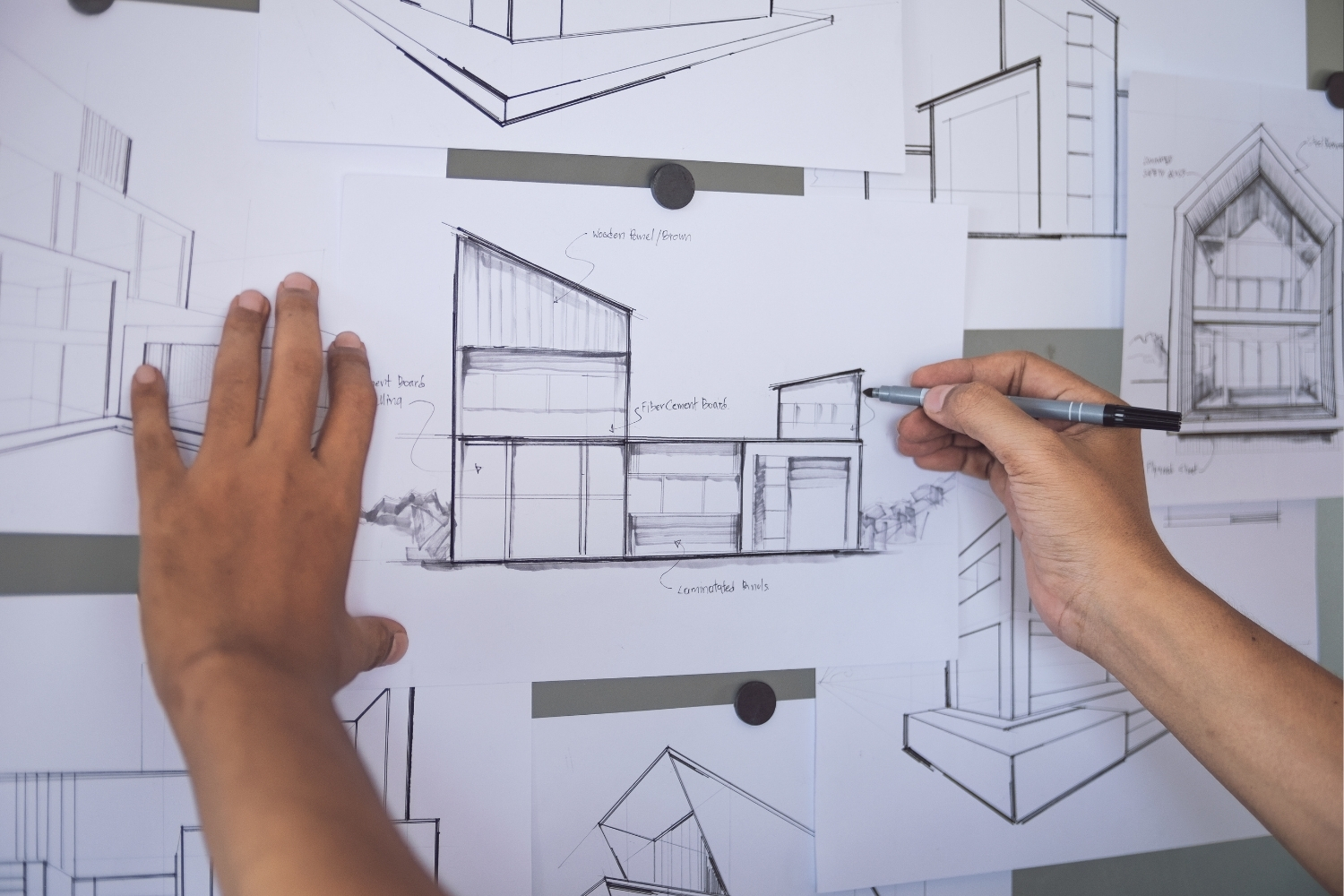
The Two-Dimensional Drawing Types
Most working drawings are orthographic, meaning they show the building straight on with no perspective distortion, so every measurement stays true to scale. These flat views form the backbone of any drawing set.Floor Plans
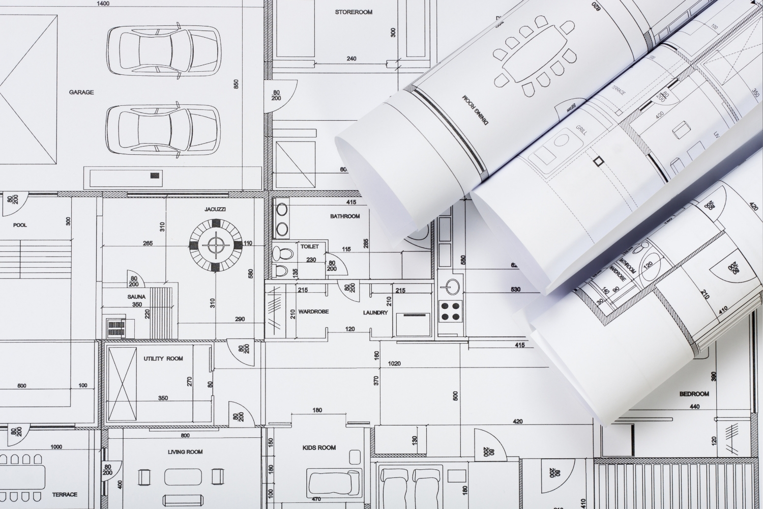
A floor plan is a horizontal slice through the building, usually taken about 1.2 meters (4 feet) above the floor and viewed from above. It shows room layouts, wall positions, doors, windows, and circulation. Plans are the most referenced drawing in any set because almost every other drawing connects back to them. If you master one drawing type first, make it the plan. Our guide to creating architectural floor plans covers the conventions in more depth.📌 Did You Know?
The 1.2 meter (4 foot) cut height for floor plans is not arbitrary. At that level the slice reliably passes through windows, doors, and counter-height elements, while staying below most ceiling-mounted fixtures. Anything on the ceiling gets its own reflected ceiling plan instead.
Site Plans
A site plan zooms out to show the building on its plot, including boundaries, access roads, landscaping, parking, and utility connections. Planning authorities almost always require one before granting permission, since it shows how the project sits within its surroundings and respects setbacks and property lines.Elevations
An elevation is a flat, head-on view of one vertical face of the building, drawn to scale. It shows heights, proportions, materials, and the placement of windows and doors without perspective. Most projects need at least four, and the front elevation gets the most scrutiny in planning reviews, since professional bodies such as the American Institute of Architects treat elevations as standard permit documents. See our breakdown of elevation drawings for the main subtypes.Section Drawings
A section cuts vertically through the building to reveal what plans and elevations hide: floor-to-floor heights, ceiling volumes, structural depth, and how spaces stack and connect. Sections are where you understand how light enters and how a building actually feels inside. They range from full-building cuts at 1:100 down to detailed wall sections. Our collection of architectural section drawings shows how leading architects use them.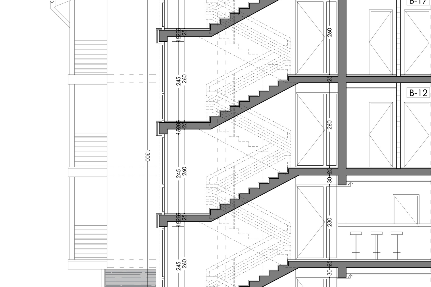
Detail Drawings
A detail drawing zooms into a specific junction (a window head, a parapet, a foundation edge) at a large scale like 1:5 or 1:10. Where a plan shows a wall as a single line, the detail reveals every material layer, fastener, and dimension a contractor needs. A mid-size project can include dozens of these, and they carry real contractual weight, which is why precision matters. Our guide to architectural detail drawings walks through how to produce them.💡 Pro Tip
Keep your line weights consistent across every drawing in a set. Use heavy lines for elements the cut plane passes through, medium lines for edges seen beyond the cut, and light lines for surface texture or hidden elements. A reviewer reads line weight before they read labels, so inconsistent weights make even a careful drawing look unresolved.
The Three-Dimensional and Freehand Types
Beyond the flat orthographic set, architects use drawings that capture depth and volume, or that simply think out loud on paper. Studying real examples helps here, and archives like ArchDaily’s architectural drawing collection show how practicing architects handle each type.Axonometric and Isometric Drawings
Axonometric drawings are a form of parallel projection that show three sides of a building at once while keeping measurements true along each axis. Unlike perspective, lines never converge, so you can scale directly off the drawing. Isometric is one specific subset where all three axes sit at equal angles. These views are popular for exploded diagrams that pull a building apart layer by layer. Our explainer on axonometric drawings covers the projection types.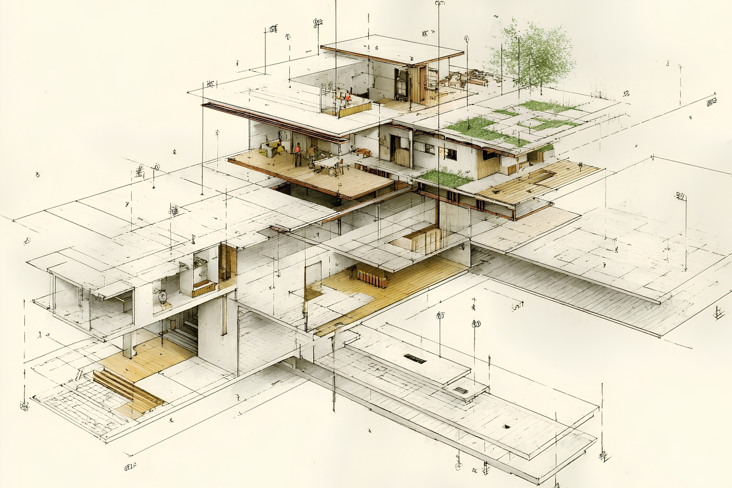
Perspective Drawings
A perspective drawing mimics how the human eye actually sees, with lines converging toward one, two, or three vanishing points. This makes it the most realistic and intuitive view for clients, but it distorts scale, so it works as a communication tool rather than a measured document. Perspectives are strongest in presentations and competition boards where atmosphere matters more than dimensions.Concept Sketches
Concept sketches are fast, freehand drawings made to test and develop an idea before any precise work begins. They are thinking tools, not presentation pieces, and they stay deliberately rough. Many respected architects, including Le Corbusier and Renzo Piano, relied on hand sketches throughout their careers because drawing by hand forces quicker decisions. These early studies often sit alongside architectural diagrams, which serve a related but distinct role.
Quick Comparison of the Main Drawing Types
The table below summarizes what each drawing type shows and when you are most likely to use it:| Drawing Type | What It Shows | Typical Use |
|---|---|---|
| Floor Plan | Room layout from above | Design and construction |
| Site Plan | Building on its plot | Planning permission |
| Elevation | One vertical face | Facade design, permits |
| Section | Vertical cut, interior heights | Spatial and structural design |
| Detail Drawing | Close-up of a junction | Construction documentation |
| Axonometric | 3D view, true to scale | Diagrams, system breakdowns |
| Perspective | 3D view, realistic depth | Client presentations |
| Concept Sketch | Rough idea study | Early design exploration |
Where to Go From Here
Your next step: pick one building you admire and try drawing its plan, one elevation, and a section, even roughly. Producing all three for a single project teaches you how the drawing types lock together far faster than studying each one on its own.Frequently Asked Questions
What are the main types of architectural drawings?
The core types are floor plans, site plans, elevations, sections, and detail drawings, which are all orthographic, plus axonometric views, perspectives, and concept sketches. Plans, sections, and elevations are often called the three fundamental drawing types because together they describe a building completely.What is the difference between a plan and a section?
A plan is a horizontal cut viewed from above, showing room layout and circulation. A section is a vertical cut viewed from the side, showing heights, levels, and how floors stack. Plans answer “where,” while sections answer “how tall and how connected.”Which architectural drawing should a student learn first?
Start with the floor plan. It is the most referenced drawing in any set, and nearly every other drawing type, from sections to elevations, ties back to it. Once plans feel natural, move on to sections and elevations.Are architectural drawings made by hand or by computer?
Both. Most final construction drawings are produced in CAD or BIM software such as AutoCAD or Revit, while early concept sketches and study drawings are often done by hand. Many architects still sketch by hand to think, then refine digitally for presentation and documentation.


How to Draw Architectural Plans by Hand: A Step-by-Step Guide
A practical, step-by-step breakdown of drawing architectural plans by hand, from choosing...

Best Stylus and Pen for Architectural Sketching: Top Picks for 2026
A tested breakdown of the top stylus pens and traditional pens for...

Unlocking Creativity: The Power of Sketching in Architectural Design
Discover the vital role of sketching in architectural design through our comprehensive...

Elevation Drawing in Architecture: Types, Tools & Best Practices
Elevation drawings are scaled, two-dimensional representations of a building's vertical faces used...

Leave a comment