

How to Draw Architectural Plans by Hand: A Step-by-Step Guide
A practical, step-by-step breakdown of drawing architectural plans by hand, from choosing the right drafting tools and setting a proper scale to laying out walls, placing doors and windows, adding dimensions, and producing a finished floor plan ready for client review or permit submission.

Table of Contents Show
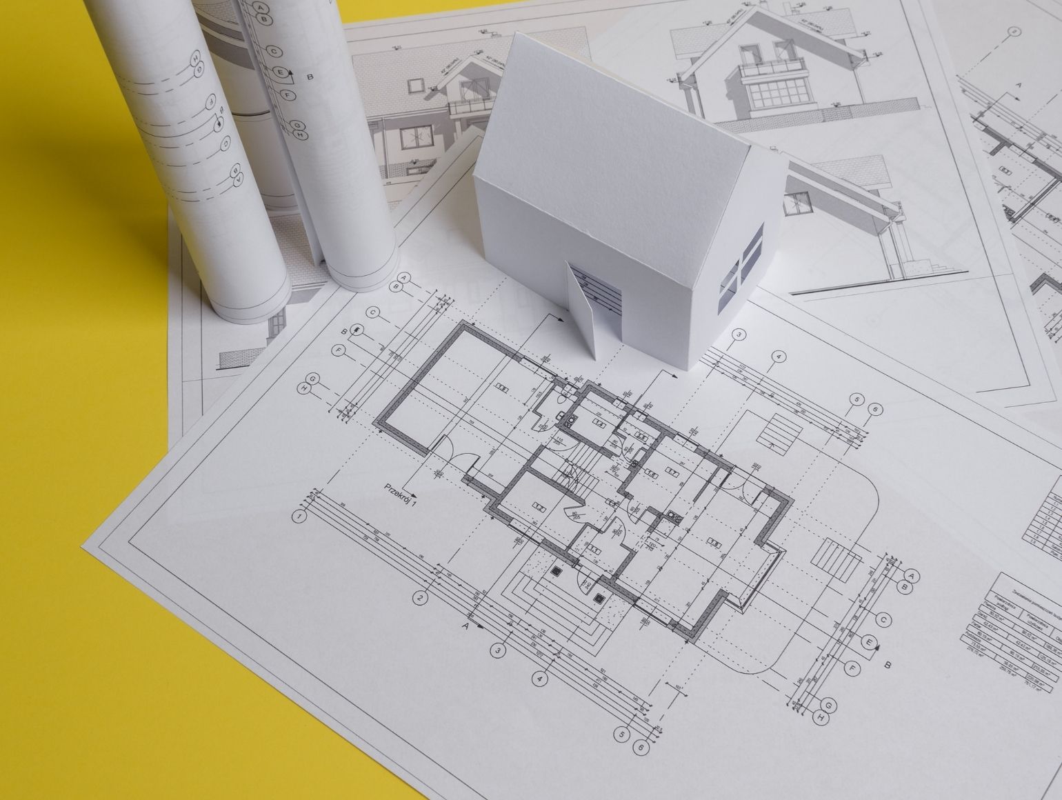
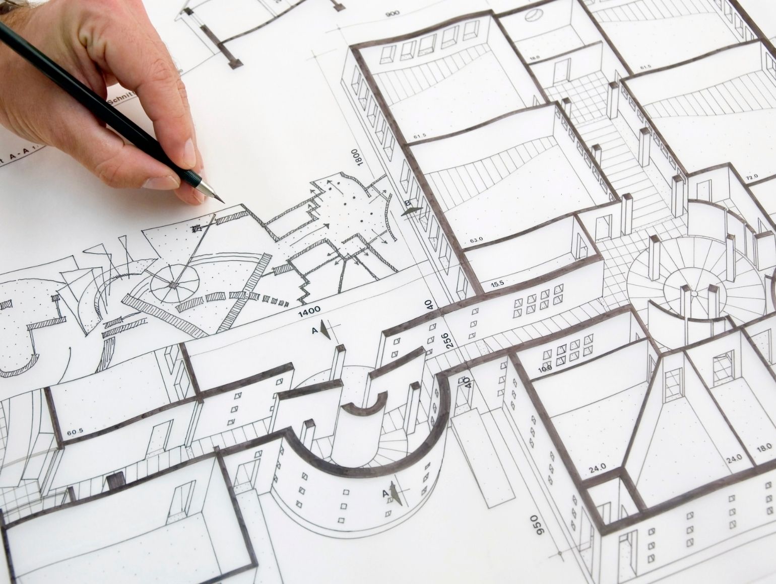
An architectural plan drawn by hand is a scaled, top-down technical drawing that shows walls, doors, windows, dimensions, and spatial relationships of a building on paper. Hand drafting remains a valued skill for architects, students, and designers who need to sketch ideas quickly, communicate spatial concepts during early design phases, or produce drawings when software is not available.
Even in an era dominated by CAD and BIM software, the ability to draw architectural plans by hand gives you a direct connection to proportion, scale, and spatial thinking that no screen can fully replace. Hand-drawn floor plans force you to slow down, consider every line, and develop a physical understanding of the space you are designing. For architecture students, hand drafting is still a core requirement in most programs worldwide. For practicing professionals, a quick hand-drawn architectural plan on trace paper can resolve a design problem in minutes during a site meeting, long before a laptop boots up.
This guide walks you through the entire process of drawing an architectural plan by hand, from selecting the right tools and choosing a scale to laying out walls, placing openings, adding dimensions, and finishing the drawing for presentation or permit submission.
Essential Tools for Drawing Architectural Plans by Hand
Before you start drawing, gather the right equipment. Using proper drafting tools makes a significant difference in accuracy and line quality. A hand-drawn architectural floor plan produced with the right instruments looks professional and communicates clearly. One produced with whatever pen was lying around does not.
Pencils and Lead Grades
Mechanical pencils are the standard for architectural drafting. A 0.5 mm lead holder with HB lead works well for general lines, while a 0.3 mm pencil with 2H lead is better suited for light construction lines and guidelines. For darker outlines and section cuts, switch to a 0.7 mm pencil with B or 2B lead. Having at least three pencils loaded with different lead grades saves time and keeps your line weights consistent throughout the drawing.
If you prefer traditional wooden drafting pencils, keep a sandpaper pad nearby to maintain a sharp chisel point. A dull pencil produces thick, fuzzy lines that make dimensions hard to read and walls look imprecise.
Paper, Scales, and Drafting Equipment
Use tracing paper (90 gsm or higher) or vellum for final drawings. Grid paper with a 5 mm grid works well for initial layouts because it provides a built-in reference for keeping lines straight and maintaining proportions without constantly reaching for a ruler. For the final draft, switch to smooth tracing paper or a sheet of Bristol board.
An architectural scale ruler is essential. Triangular scale rulers display multiple scales on a single tool, typically including 1:50, 1:100, and 1:200 for metric users, or 1/4″ = 1′-0″ and 1/8″ = 1′-0″ for imperial. Other tools you will need include a T-square or parallel bar, a 30/60 and 45-degree triangle set, a compass, a circle template, an eraser shield, and drafting tape to hold your sheet in place.
📐 Technical Note
Standard architectural drawing sheet sizes follow ISO 216 (A-series) or ANSI/ASME Y14.1 specifications. A1 (594 x 841 mm) is the most common sheet size for residential floor plans drawn at 1:50 scale. In the United States, ARCH D (24 x 36 inches) is the equivalent standard. Choosing a sheet size that fits your plan at the chosen scale, with room for a title block and dimensions, prevents the need to redraw on a larger sheet later.
How to Set Up Your Drawing Sheet
Tape your paper to a flat drawing board or drafting table with small pieces of drafting tape at each corner. Leave at least 25 mm (1 inch) of margin on all sides. Draw a border line and a title block in the lower-right corner. The title block should include the project name, drawing title (e.g., “Ground Floor Plan”), scale, date, drawn-by name, and a north arrow.
Choosing the Right Scale for Your Architectural Floor Plan
Scale selection depends on the size of the building and the amount of detail you need to show. For a single-family house, 1:50 (metric) or 1/4″ = 1′-0″ (imperial) gives you enough room to show wall thicknesses, door swings, and furniture layouts. For larger buildings or multi-story projects, 1:100 or 1/8″ = 1′-0″ keeps the drawing on a manageable sheet. Detailed areas like bathrooms and kitchens sometimes need a separate enlarged plan at 1:20 or 1/2″ = 1′-0″.
Write the scale clearly on the sheet, and draw a graphic scale bar below the title block. A graphic scale bar remains accurate even when the drawing is photocopied or printed at a different size, while a written scale like “1:50” becomes misleading if the sheet is reduced.
For a deeper look at how architectural plans are structured and presented, the guide on tips for creating and presenting architectural plans covers layout conventions and software alternatives.
Step-by-Step Process for Drawing an Architectural Plan by Hand
The following eight steps take you from a blank sheet to a finished hand-drawn architectural plan. Each step builds on the previous one, so resist the urge to skip ahead and add detail before the basic layout is locked in.
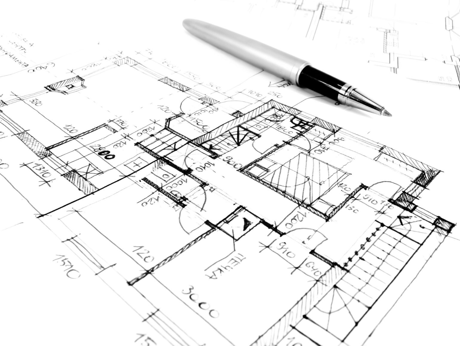
Step 1: Measure the Space and Gather Reference Data
If you are drawing an existing building, measure every room with a laser distance meter or a long tape measure. Record wall lengths, door widths, window positions measured from the nearest corner, and ceiling heights. Sketch a rough freehand plan on a clipboard as you go, and write all measurements directly on the sketch. Double-check critical dimensions by measuring the overall length of a wall and comparing it to the sum of the individual room widths along that wall.
If you are designing a new building, start with a program document or bubble diagram that defines the required rooms, their approximate sizes, and their relationships. Having this information organized before touching the drafting paper prevents false starts. You can learn more about architectural sketching fundamentals for beginners to develop this early-stage skill.
Step 2: Draw the Outer Walls
Using your chosen scale, draw the outer boundary of the building with light construction lines first. Mark the overall length and width, then draw two parallel lines to represent each external wall, separated by the wall thickness. Standard exterior wall thicknesses for residential buildings range from 200 mm to 300 mm (8 to 12 inches) depending on the construction system: timber frame, masonry, or insulated concrete forms.
Use your T-square for horizontal lines and your triangle for vertical ones. Keep all lines light at this stage. You will darken them later when you apply final line weights.
💡 Pro Tip
Draw all construction lines with a hard lead (2H or 3H) so they are easy to erase later. Press lightly and keep a consistent, barely-visible line. Experienced drafters build the entire plan in construction lines first and only switch to softer leads (HB or B) for the final pass, reducing errors and erasing time by more than half.
Step 3: Add Interior Walls and Partitions
With the exterior shell in place, draw interior walls. Interior partition walls in residential buildings are typically 100 mm to 150 mm (4 to 6 inches) thick. Load-bearing interior walls match or come close to exterior wall thickness. Mark each wall’s position by measuring from the nearest exterior wall or from a grid line if you are working on a structural grid.
Keep your rooms proportional and check that corridors meet minimum width requirements. Residential hallways should be at least 900 mm (36 inches) wide, and building codes in most jurisdictions require a minimum clear width of 1,050 mm (42 inches) for accessible routes. The Americans with Disabilities Act (ADA) and similar accessibility standards in other countries specify these clearances in detail.
Step 4: Place Doors and Windows
Doors and windows are drawn as breaks in the wall line. For a standard hinged door, erase the wall segment at the door location, draw a thin line representing the door leaf, and add a quarter-circle arc showing the swing direction. Standard interior door widths are 762 mm (30 inches) or 813 mm (32 inches), while main entry doors are typically 914 mm (36 inches).
Windows are shown as a break in the wall with two or three parallel lines inside the wall thickness, depending on your drawing convention. Mark the distance from the nearest corner to the edge of each window opening. Consistent symbol use matters: pick one convention and apply it across the entire drawing.
Step 5: Add Stairs, Built-In Elements, and Fixtures
Draw stairs with parallel lines for each tread, an arrow indicating the direction of travel (up or down), and the number of risers noted. Kitchen counters, bathroom fixtures (toilet, sink, bathtub or shower), and built-in wardrobes should be drawn at this stage using standard architectural symbols. A circle template speeds up the process for drawing sinks, toilet bowls, and column sections.
For detailed guidance on the symbols and conventions used across different drawing types, the article on architectural section drawings and techniques provides a strong reference.
🎓 Expert Insight
“Drawings are not just technical instruments; they are a form of thinking. When you draw by hand, you discover things about a design that no computer can reveal.” — Renzo Piano, Renzo Piano Building Workshop
Piano, a Pritzker Prize laureate, has spoken repeatedly about maintaining a hand-drawing practice alongside digital tools. His observation highlights that the hand-drawn architectural plan is not just a deliverable but a design thinking exercise in itself.
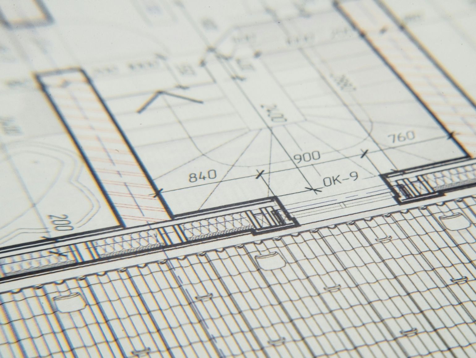
Step 6: Include Dimensions and Annotations
Dimensioning is what turns a sketch into a usable architectural plan. Place dimension lines outside the building outline in three tiers: the first row for individual room and opening dimensions, the second for cumulative wall-to-wall dimensions, and the third for the overall building dimension. Use a consistent dimension line style with ticks or arrowheads at each end, and write the measurement above the line in a clear, upright lettering style.
Inside the plan, label each room with its name and area in square meters or square feet. Add notes for floor finishes, ceiling heights where they change, and any structural elements like columns or beams shown in dashed lines above the cut plane.
Good architectural lettering is as important as accurate linework. Practice a consistent, slightly condensed uppercase style. All text on architectural plans should be legible at the intended print size, which typically means 2.5 mm to 3.5 mm letter height for notes and 5 mm for room labels. The ISO 3098 standard specifies lettering requirements for technical drawings.
Step 7: Apply Line Weights and Hatching
Line weight hierarchy is what gives a hand-drawn plan its depth and readability. Walls that are cut by the plan (the walls you would see if you sliced horizontally through the building at about 1.2 meters above the floor) should be the thickest lines, drawn with a soft lead (B or 2B) or a 0.5 to 0.7 mm technical pen. Elements below the cut plane, like floor tiles or steps, get medium-weight lines. Elements above, like overhead cabinets or beams, are shown with dashed lines at a lighter weight.
Add material hatching where required: diagonal lines for concrete, cross-hatching for masonry, and a wood grain pattern for timber sections. Fill the wall sections (poché) with solid black or dense hatching to make the plan immediately readable. This single step transforms a flat diagram into a drawing that communicates structure and materiality.
💡 Pro Tip
Before committing to final line weights on your good sheet, do a quick test strip on a scrap piece of the same paper. Draw three lines with the lead grades and pressures you plan to use, then photocopy or scan the strip. Lines that look distinct on the original can merge when reproduced. Adjusting your line weight hierarchy before inking the final plan saves hours of rework.
Step 8: Review, Clean, and Finalize the Plan
Go over the entire drawing systematically. Check that all dimensions add up, that door swings do not collide with furniture or other doors, and that room labels are complete. Use an eraser shield to clean up stray marks without disturbing nearby lines. Remove any remaining construction lines with a soft eraser.
Add a north arrow, the graphic scale bar, and complete the title block. If the plan will be submitted for a building permit, verify that it meets the local authority’s submission requirements for sheet size, scale, and required information. You can find more practical advice on finalizing and presenting plans in the article on how to present better architectural plans.
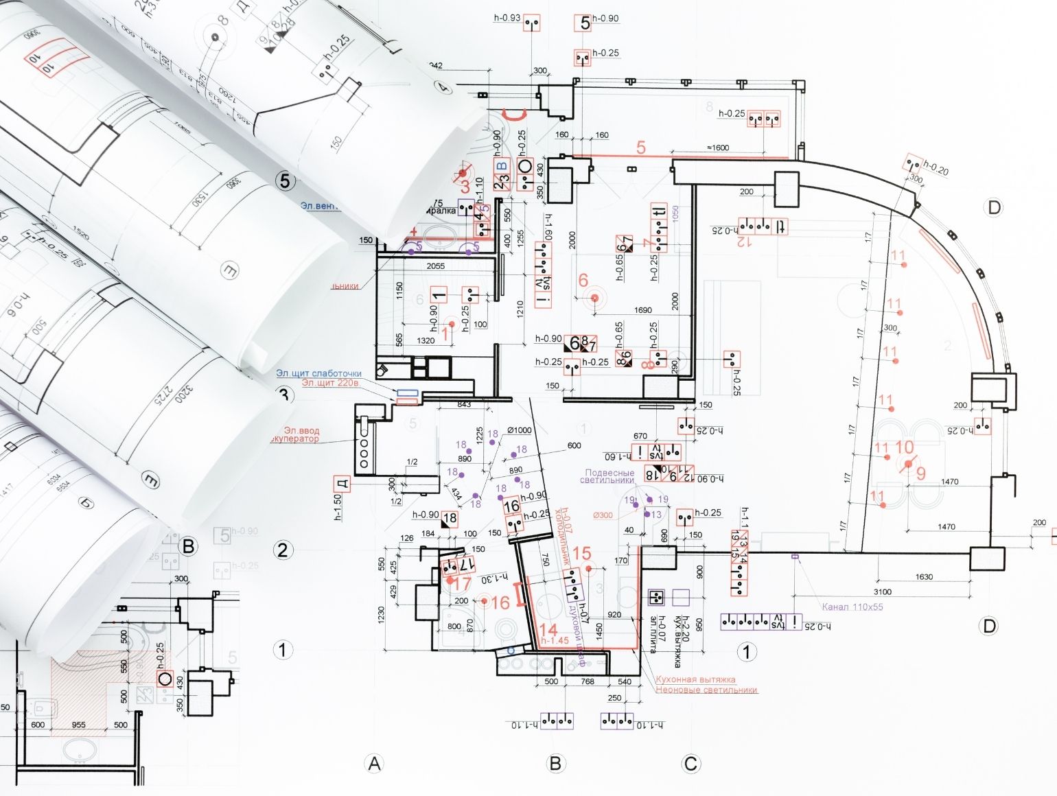
What Are the Standard Symbols Used in Architectural Floor Plans?

Architectural floor plans use a standardized set of symbols so that anyone reading the drawing, whether an engineer, contractor, or building inspector, can interpret it without ambiguity. Doors are represented by a line and an arc showing the swing. Windows appear as parallel lines within the wall. Stairs are drawn with parallel tread lines and a directional arrow. Columns are shown as filled or outlined rectangles or circles, depending on the material.
Other common symbols include section cut indicators (a circle with a line and number referencing the section drawing), elevation markers, level indicators, and north arrows. Plumbing fixtures, electrical outlets, and switches each have their own symbols defined in national standards such as AIA graphic standards in the United States or RIBA conventions in the United Kingdom.
Consistency is the most important rule. If you use a single line for a door on one floor, use the same representation on every floor. Mixed conventions on a single drawing set create confusion that leads to construction errors.
Why Hand-Drawn Architectural Plans Still Matter
Digital tools are faster for production drawings, and no one disputes that. But hand drafting remains relevant for several reasons. First, architecture schools worldwide continue to teach hand drawing as a foundational skill because it builds an intuitive sense of scale and proportion that transfers directly to digital work. Second, hand-drawn architectural plans are faster to produce during early design meetings, charrettes, and site visits where a laptop is impractical. Third, clients and review panels often respond more positively to hand-drawn presentations because they signal design intention rather than finished production, inviting feedback rather than closing the conversation.
The link between hand and mind is well documented in architectural pedagogy. Improving your architectural drawing skills strengthens spatial reasoning, speeds up your ability to visualize three-dimensional spaces from two-dimensional representations, and helps you spot design problems earlier in the process.
📌 Did You Know?
Frank Lloyd Wright produced nearly all of his architectural plans by hand throughout his 70-year career, including the drawings for Fallingwater (1935) and the Solomon R. Guggenheim Museum (1959). His original hand-drafted plans are now preserved at the Museum of Modern Art and Columbia University’s Avery Architectural and Fine Arts Library, with over 20,000 drawings in the collection.
Common Mistakes When Drawing Architecture Plans by Hand
Beginners and even intermediate drafters tend to repeat a few predictable mistakes. Recognizing these early can save significant time and frustration.
Starting with too much detail too soon is the most frequent problem. If you begin inking walls and adding hatching before the overall layout is confirmed, a single dimensional error forces you to redraw large sections. Always work from light construction lines to dark final lines, and confirm all major dimensions before committing to permanent marks.
Ignoring line weight hierarchy is equally damaging. A plan drawn entirely in one line weight looks flat and is difficult to read. Cut walls must be visually dominant. Without this contrast, the drawing fails its primary job: communicating where space begins and structure ends.
Poor lettering undermines otherwise excellent drawings. If your dimensions and labels are sloppy, reviewers will question the accuracy of everything on the sheet. Practice uniform lettering on a separate sheet until it becomes second nature.
⚠️ Common Mistake to Avoid
Many students draw walls as single lines instead of double lines with proper thickness. A single-line wall is a diagram, not an architectural plan. It cannot show door frames, window reveals, or material sections accurately. Always draw walls as two parallel lines separated by the actual wall thickness at the chosen scale, even if it seems like extra work at the beginning.
Video: How to Sketch a Floor Plan by Hand
This beginner-friendly tutorial walks through the full process of sketching a floor plan from scratch, covering measuring, layout, and finishing steps.
✅ Key Takeaways
- Start every hand-drawn architectural plan with light construction lines using hard lead (2H or 3H), and only darken final lines after confirming all dimensions.
- Choose a scale that fits your building on the sheet with room for dimensions and a title block. For most residential plans, 1:50 (metric) or 1/4″ = 1′-0″ (imperial) works best.
- Line weight hierarchy is what separates a professional architectural floor plan from a flat diagram. Cut walls must always be the thickest, darkest lines on the sheet.
- Dimension your plan in three tiers outside the building outline: individual openings, wall-to-wall cumulative, and overall building dimension.
- Consistent use of standard symbols for doors, windows, stairs, and fixtures makes your drawing readable to engineers, contractors, and building officials without additional explanation.
Final Thoughts
Drawing an architectural plan by hand is a methodical process that rewards patience and accuracy. Every line on the sheet carries information, from the thick poché of a cut wall to the thin dashed line of a beam overhead. Mastering this process does not just produce better hand-drawn plans; it makes you a better designer. The spatial awareness and proportional judgment you develop at the drafting table carry over directly into every digital tool you use later.
If you are just starting out, pick a simple room, gather your tools, and work through the eight steps above at a comfortable pace. Accuracy matters more than speed at this stage. With each plan you complete, the process becomes faster and the results get cleaner. For further reading on sketching and drawing techniques, the guide to architecture sketch techniques and modern practices covers both hand and hybrid workflows in detail.
Frequently Asked Questions

What pencil is best for drawing architectural plans by hand?
Mechanical pencils with 0.5 mm lead in HB grade are the most versatile choice for general drafting. Use harder leads (2H) for construction lines and softer leads (B or 2B) for darkened final walls and section cuts. Having multiple pencils loaded with different grades lets you switch quickly without interrupting your workflow.
How long does it take to draw an architectural floor plan by hand?
A simple residential floor plan at 1:50 scale typically takes 4 to 8 hours for an experienced drafter, including dimensioning and title block completion. Beginners should expect to spend 10 to 15 hours on the same plan. Speed improves significantly after the first three or four complete plans, as muscle memory and convention recall become automatic.
Can hand-drawn architectural plans be submitted for building permits?
Yes, most building departments accept hand-drawn plans as long as they meet the jurisdiction’s requirements for scale, clarity, required information, and sheet size. Some jurisdictions now require digital submissions, so check with your local planning authority before starting. The drawing quality and completeness matter more than whether the plan was produced by hand or by software.
What scale should I use for a residential floor plan?
For metric users, 1:50 is the standard scale for residential architectural floor plans, offering enough detail to show wall thicknesses, door swings, and furniture. For imperial users, 1/4″ = 1′-0″ is the equivalent. Larger buildings or site plans use 1:100 or 1:200 to fit on a single sheet.
What is the difference between an architectural plan and a floor plan?
An architectural plan is a broad category that includes all scaled drawings used in building design: floor plans, site plans, roof plans, ceiling plans, and demolition plans. A floor plan is one specific type of architectural plan that shows a horizontal cross-section of a single building level, typically cut at about 1.2 meters above the floor. Every floor plan is an architectural plan, but not every architectural plan is a floor plan. You can read a full breakdown in the guide to architectural plans.
- architectural design house plans
- architectural floor plan
- Architectural Floor Plans
- architectural home plans
- architectural house design plans
- architectural plan
- architectural plan made by hand steps
- Architectural Plans
- architecture floor plan
- Architecture Plans
- draw architectural plans by hand
- how to draw architectural plans by hand


Architectural Drawings: A Student’s Guide to 8 Essential Types
A clear introduction to the eight architectural drawing types every student meets...

Best Stylus and Pen for Architectural Sketching: Top Picks for 2026
A tested breakdown of the top stylus pens and traditional pens for...

Architecture Sketch: Essential Techniques and Modern Practices
Table of Contents Show Core Principles of Architectural SketchingWhat Is an Architectural...

From Concept Sketch to Builder-Ready Blueprint
Table of Contents Show The Role of the Concept SketchBubble Diagrams as...

Leave a comment