

Architectural Site Plan: A Practical Guide to Elements, Types & Drawing Tips
This guide breaks down the architectural site plan from its core elements and standard symbols to the step-by-step process of drawing one. Covers site plan types, software tools, common mistakes, and the differences between site plans and floor plans, with practical tips for students and professionals.

Table of Contents Show
What Is an Architectural Site Plan?
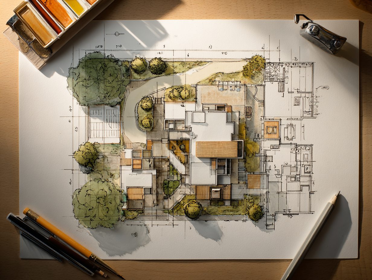
 A site plan (sometimes called a plot plan) is an architectural drawing that maps proposed and existing conditions on a specific parcel of land. It is drawn to scale, typically viewed from directly above, and includes every element that affects how the building relates to its lot and surroundings. Where a floor plan cuts horizontally through a building’s interior to reveal room layouts, the site plan pulls the camera much further back. It captures the full property, its edges, and the context beyond those edges.
The purpose of a site plan goes well beyond design presentation. Municipalities require one for virtually every building permit application, because it is the only drawing that proves compliance with setback regulations, parking requirements, lot coverage ratios, and easement restrictions. Landscape architects rely on it to coordinate grading, planting, and irrigation. Civil engineers use it to plan stormwater drainage, utility connections, and road access. Contractors reference it to organize staging areas, equipment placement, and construction sequencing. Without a site plan, a project has no spatial anchor.
A site plan (sometimes called a plot plan) is an architectural drawing that maps proposed and existing conditions on a specific parcel of land. It is drawn to scale, typically viewed from directly above, and includes every element that affects how the building relates to its lot and surroundings. Where a floor plan cuts horizontally through a building’s interior to reveal room layouts, the site plan pulls the camera much further back. It captures the full property, its edges, and the context beyond those edges.
The purpose of a site plan goes well beyond design presentation. Municipalities require one for virtually every building permit application, because it is the only drawing that proves compliance with setback regulations, parking requirements, lot coverage ratios, and easement restrictions. Landscape architects rely on it to coordinate grading, planting, and irrigation. Civil engineers use it to plan stormwater drainage, utility connections, and road access. Contractors reference it to organize staging areas, equipment placement, and construction sequencing. Without a site plan, a project has no spatial anchor.
💡 Pro Tip
Before starting your site plan, obtain a recent land survey from a licensed surveyor. Relying on outdated surveys or satellite imagery alone can introduce boundary errors of 30 cm or more, which is enough to trigger setback violations during the permit review.
Key Elements of an Architectural Site Plan
A complete site plan communicates a large amount of information in a single drawing. Each element serves a specific audience, whether that is a zoning officer checking setbacks, a contractor planning excavation, or a landscape architect coordinating planting zones. Below are the elements you will find on most professional site plans.Property Boundaries and Dimensions
Property lines define the legal limits of the parcel. They are drawn using boundary data from a registered land survey and annotated with precise dimensions in meters or feet. Boundary markers, corner coordinates, and any encroachments from neighboring properties are recorded. These lines are the foundation of every other measurement on the drawing, because setback distances, lot coverage calculations, and building placement all reference them.Building Footprint and Setback Lines
The proposed structure appears as a simplified outline, often hatched or shaded to distinguish it from existing buildings on the site. Setback lines are drawn parallel to property boundaries, indicating the minimum distance a building must maintain from lot edges according to local zoning regulations. The gap between the building footprint and the setback line confirms compliance at a glance.Topography and Grading
Contour lines represent the existing terrain, with each line connecting points of equal elevation. Spot elevations at key locations, such as building corners, curb edges, and drainage inlets, supplement the contour data. Proposed grading changes show how the land will be reshaped during construction to direct water away from the building and toward stormwater management systems. On sloped sites, this layer of information is especially critical. A thorough site analysis during the early design phase identifies drainage challenges and grading opportunities before the site plan is finalized.Access, Circulation, and Parking
Driveways, pedestrian paths, service roads, and fire access lanes are shown with their widths and surface materials. Parking areas include individual space dimensions, accessible parking locations, turning radii, and traffic flow arrows. For commercial projects, site plans often show vehicle queuing areas, loading docks, and delivery routes. Municipal codes typically dictate minimum parking counts based on building use and gross floor area.Utilities and Services
Underground and overhead utilities are mapped using standardized symbols. Water supply lines, sanitary sewer connections, stormwater drains, electrical conduits, gas lines, and telecommunications cables each have their own line type or color convention. Connection points to municipal infrastructure are noted, along with utility easements that restrict where construction can occur. Accurate utility mapping prevents costly clashes during excavation.Landscaping and Vegetation
Existing trees to be retained are drawn with their canopy radius and species notation. Proposed planting areas, hardscape surfaces, retaining walls, fences, and site furniture are indicated. In many jurisdictions, tree preservation ordinances require architects to identify every tree above a specified diameter and justify any removal. Landscape architecture considerations such as irrigation zones, bioswales, and permeable paving may also appear on the site plan or on a separate landscape plan that references the same base drawing.North Arrow, Scale, and Legend
Every site plan includes a north arrow for orientation, a graphic and numeric scale (such as 1:200 or 1″=20′), and a legend explaining line types, hatching patterns, and drawing symbols. Title blocks record the project name, drawing number, revision dates, and the licensed professional’s stamp or seal. These elements are not decorative; they make the drawing legally and professionally valid.📐 Technical Note
Common site plan scales range from 1:100 to 1:500 for residential projects and 1:500 to 1:2000 for large commercial or campus developments. The International Organization for Standardization (ISO 5455) defines preferred scale ratios for technical drawings. Choosing the right scale ensures that all required detail is legible without the drawing becoming unmanageably large.
How Does a Site Plan Differ from a Floor Plan?
 This is one of the most common points of confusion for people new to architectural drawings. A floor plan is a horizontal cut through the interior of a building, typically taken at about 1.2 meters above floor level. It reveals walls, rooms, doors, windows, and furniture layouts. A site plan, by contrast, shows the entire property from above, including the building as a simple footprint, plus everything that surrounds it.
Think of it this way: the floor plan answers “What happens inside the building?” while the site plan answers “How does the building sit on the land?” Both are produced for every project, and both appear in every permit submission, but they communicate fundamentally different information. Reading the floor plan without referencing the site plan means you cannot evaluate orientation, solar access, vehicular approach, or setback compliance. For a deeper look at floor plan conventions, the architecture floor plan guide covers the elements and drawing methods in detail.
This is one of the most common points of confusion for people new to architectural drawings. A floor plan is a horizontal cut through the interior of a building, typically taken at about 1.2 meters above floor level. It reveals walls, rooms, doors, windows, and furniture layouts. A site plan, by contrast, shows the entire property from above, including the building as a simple footprint, plus everything that surrounds it.
Think of it this way: the floor plan answers “What happens inside the building?” while the site plan answers “How does the building sit on the land?” Both are produced for every project, and both appear in every permit submission, but they communicate fundamentally different information. Reading the floor plan without referencing the site plan means you cannot evaluate orientation, solar access, vehicular approach, or setback compliance. For a deeper look at floor plan conventions, the architecture floor plan guide covers the elements and drawing methods in detail.
⚠️ Common Mistake to Avoid
Many architecture students submit a floor plan when their brief calls for a site plan, or vice versa. Double-check your deliverable list. A floor plan shows interior room layouts; a site plan shows the building’s position on the lot with boundaries, access, and context. Submitting the wrong drawing type at a planning meeting or jury review is a mistake that undermines credibility.
Comparison of Site Plan vs Floor Plan
The table below summarizes the key differences between these two drawing types:| Feature | Site Plan | Floor Plan |
|---|---|---|
| View | Bird’s-eye view of entire property | Horizontal cut through one floor level |
| Scale | 1:200 to 1:2000 (broader coverage) | 1:50 to 1:200 (closer detail) |
| Shows | Boundaries, topography, access, utilities, landscaping | Walls, rooms, doors, windows, furniture |
| Primary audience | Planning authorities, civil engineers, landscape architects | Interior designers, contractors, clients |
| Building detail | Simplified outline (footprint only) | Detailed internal layout |
| Regulatory role | Proves setback, parking, and zoning compliance | Proves room sizes, egress, and accessibility |
Types of Architectural Site Plans
Not every site plan is the same. The level of detail, the information emphasized, and the audience it targets vary depending on the project phase and purpose. Here are the main types architects and planners work with.Preliminary Site Plan
Also called a site sketch or concept site plan, this is the earliest iteration. It is often hand-drawn or produced quickly in CAD, showing the approximate building position, major access points, and general landscape zones. Developers use preliminary site plans to test feasibility, evaluate lot options, and hold initial conversations with planning departments before investing in detailed design. At this stage, the goal is to answer a basic question: can the intended building program fit on this parcel while meeting zoning rules?Detailed Site Plan (Construction Site Plan)
This is the fully engineered version submitted with building permit applications. It includes precise dimensions, utility connection coordinates, grading calculations, stormwater management details, and material specifications for paving, fencing, and hardscape. Civil engineers, landscape architects, and the project architect all contribute to this drawing. Accuracy is critical here, because errors can result in permit rejection or costly field revisions.As-Built Site Plan
Produced after construction is complete, the as-built site plan documents the final, actual conditions on the ground. It records any deviations from the original permitted plan, such as adjusted utility routes or modified grading. As-built plans become part of the property’s permanent record and are referenced in future renovations, expansions, or property transfers.Master Site Plan
Large developments like university campuses, hospital complexes, or mixed-use neighborhoods use master site plans that cover the entire development area across multiple phases. These plans coordinate building placement, road networks, open spaces, utility corridors, and pedestrian circulation at a scale that individual building site plans cannot address. The architectural zoning diagram often serves as an early precursor to the master site plan, mapping functional zones before detailed design begins.🎓 Expert Insight
“The site plan is the first agreement between architect and landscape. Get it wrong, and every drawing that follows inherits the error.” — Licensed architect with 20+ years of practice in urban residential projects
This observation highlights why experienced firms treat the site plan as a foundational document rather than a formality. Errors in boundary placement or setback measurement at the site plan stage cascade into every subsequent drawing, from floor plans to structural layouts.
Site Planning in Architecture: The Process
 Site planning architecture is the broader discipline of organizing buildings, circulation, landscaping, and infrastructure on a piece of land. The architectural site plan is the primary output of this process, but the process itself involves analysis, strategy, and iteration long before any drawing is finalized.
Step 1: Site Survey and Data Collection
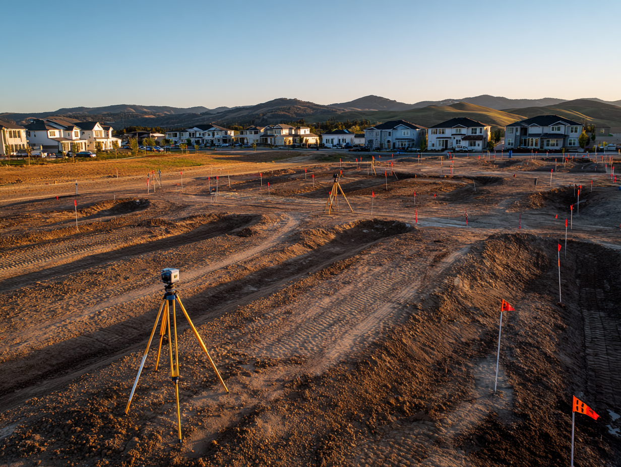
A licensed surveyor produces a boundary and topographic survey that records property lines, elevation data, existing structures, vegetation, and utility locations. This survey becomes the base layer for all subsequent site plan work. Supplementary data includes soil reports (from geotechnical engineers), flood zone maps, environmental assessments, and municipal zoning ordinances. In many regions, GIS data from local planning departments is publicly available and provides additional layers like parcel boundaries, aerial imagery, and utility corridors. For more on the analysis phase, the site analysis and site visit guide covers the full methodology.Step 2: Zoning and Regulatory Analysis
Before placing a single line, the architect reviews local zoning codes to establish hard constraints: maximum building height, lot coverage limits, floor area ratio (FAR), required setbacks from front, rear, and side boundaries, minimum parking counts, and any design review requirements. These parameters define the “buildable envelope” on the site, essentially the three-dimensional box within which the building must fit.Step 3: Concept Layout
With survey data and zoning constraints in hand, the architect develops preliminary building placement options. This stage often uses bubble diagrams and rough sketches to test different configurations. Key decisions at this point include building orientation (for solar access and prevailing wind response), vehicular and pedestrian entry locations, parking arrangement, and the relationship between outdoor spaces and the building envelope.Step 4: Detailed Site Plan Drawing
Once the concept is approved, the architect produces the detailed site plan using CAD or BIM software. Every element receives precise dimensions and annotations. The drawing is coordinated with the civil engineer’s grading and utility plans, the landscape architect’s planting plan, and the structural engineer’s foundation layout. Cross-referencing between these documents ensures consistency.Step 5: Review and Approval
The completed site plan is submitted to the local planning authority for review. Reviewers check setback compliance, parking counts, stormwater management, fire access, accessibility requirements, and conformity with the broader area plan. Revisions are common, and approvals may include conditions that require modifications before construction can begin.💡 Pro Tip
Schedule a pre-application meeting with your local planning department before finalizing the site plan. Many municipalities offer informal reviews where a planning officer flags potential issues early, saving weeks of formal revision cycles. This step is free in most jurisdictions and drastically reduces the risk of rejection.
What Role Does Site Planning Play in Landscape Architecture?
Site planning in landscape architecture extends the architectural site plan’s scope to include ecological systems, planting design, and outdoor human experience. While the architectural site plan focuses primarily on building placement and regulatory compliance, the landscape architect’s version adds layers for soil conditions, plant species selection, microclimates, stormwater bioretention areas, and habitat corridors. In practice, the two disciplines share the same base drawing. The architect positions the building and defines hardscape zones, while the landscape architect develops the planting plan, grading strategy, and outdoor spatial sequence. On larger projects, the landscape site plan may also include recreational areas, public plazas, and green infrastructure systems that serve the broader community. For a deeper understanding of this discipline, the landscape architecture guide on illustrarch.com explains how outdoor environments are designed for both beauty and function.🏗️ Real-World Example
Apple Park (Cupertino, 2017): Foster + Partners’ site plan for Apple’s headquarters arranged a 260,000 m² ring-shaped building on a 71-hectare campus, dedicating roughly 80% of the site to landscaped green space with over 9,000 drought-resistant trees. The site plan coordinated underground parking for 11,000 vehicles, a 1,000-seat theater, and a solar-paneled roof, all while preserving existing creek corridors. It remains one of the most ambitious examples of architectural site planning integrated with landscape design.
Software Tools for Creating Architectural Site Plans
 The tools architects use to produce site plans range from traditional drafting software to full BIM platforms that generate site plans from three-dimensional models.
AutoCAD remains the most widely used tool for 2D site plan drafting. Its precision, layer management, and extensive block libraries make it well suited for the line-heavy, annotation-dense nature of site plans. Many civil engineering firms deliver their survey and utility data in DWG format, making AutoCAD the natural choice for coordination. For more on how architects use AutoCAD across drawing types, the role of AutoCAD in architecture article provides additional context.
Autodesk Revit generates site plans from BIM models, which means the site plan updates automatically as the building design evolves. Revit handles topographic surfaces, building pads, and site components, though detailed civil engineering work (grading, utility coordination) is often completed in Civil 3D and linked back into the Revit model.
SketchUp is popular in early design phases for quick 3D site massing studies. Paired with plugins like SketchUp’s native terrain tools or third-party extensions, it can produce effective preliminary site plans. For final construction documentation, however, most firms switch to AutoCAD or Revit.
GIS platforms such as ArcGIS Pro are used when site plans need to incorporate large-scale spatial data: flood zones, census tracts, transportation networks, or environmental overlays. These tools are especially common in urban planning and architecture mapping workflows.
The tools architects use to produce site plans range from traditional drafting software to full BIM platforms that generate site plans from three-dimensional models.
AutoCAD remains the most widely used tool for 2D site plan drafting. Its precision, layer management, and extensive block libraries make it well suited for the line-heavy, annotation-dense nature of site plans. Many civil engineering firms deliver their survey and utility data in DWG format, making AutoCAD the natural choice for coordination. For more on how architects use AutoCAD across drawing types, the role of AutoCAD in architecture article provides additional context.
Autodesk Revit generates site plans from BIM models, which means the site plan updates automatically as the building design evolves. Revit handles topographic surfaces, building pads, and site components, though detailed civil engineering work (grading, utility coordination) is often completed in Civil 3D and linked back into the Revit model.
SketchUp is popular in early design phases for quick 3D site massing studies. Paired with plugins like SketchUp’s native terrain tools or third-party extensions, it can produce effective preliminary site plans. For final construction documentation, however, most firms switch to AutoCAD or Revit.
GIS platforms such as ArcGIS Pro are used when site plans need to incorporate large-scale spatial data: flood zones, census tracts, transportation networks, or environmental overlays. These tools are especially common in urban planning and architecture mapping workflows.
How to Read an Architectural Site Plan Drawing
Reading a site plan drawing requires familiarity with a few conventions that differ from floor plan reading. Start with the title block, which tells you the scale, orientation, and revision status. Find the north arrow to understand the drawing’s directional orientation relative to the real world. Then identify the property boundary, which is the outermost line on the drawing and the reference frame for everything inside it. From there, locate the building footprint (typically the largest shaded or hatched shape), setback lines (dashed lines parallel to boundaries), and access routes (driveways, paths). Contour lines show elevation changes: lines close together indicate steep slopes, and lines far apart indicate flat terrain. Utility lines are typically drawn as dashed or colored lines with labels indicating type (W for water, SS for sanitary sewer, SD for storm drain, E for electrical). For a full reference on the symbols used across all architectural drawing types, the architectural drawing symbols guide is a useful companion resource.📌 Did You Know?
The concept of the site plan dates back to ancient Roman military engineering. Roman surveyors (agrimensores) produced scaled drawings of military camp layouts (castra) that recorded building positions, road networks, and defensive perimeters relative to the surrounding terrain. These drawings functioned as the earliest known architectural site plans, and the orthographic conventions they established influenced European cartography and architectural documentation for centuries.
Common Mistakes in Architectural Site Plan Drawing
 Even experienced professionals make errors on site plans that create problems downstream. Here are the most frequent ones and how to avoid them.
Using outdated survey data is the most expensive mistake. Property boundaries shift through subdivisions, easement changes, and road widenings. Always verify that the boundary survey reflects the current legal description of the parcel. An outdated survey can place the entire building in the wrong location relative to setback lines.
Ignoring existing underground utilities leads to clashes during excavation. If the site plan does not accurately show water mains, sewer lines, and electrical conduits, contractors risk damaging them during foundation work. Request utility locator records from the relevant service providers and cross-reference them with the surveyor’s data.
Misrepresenting topography causes drainage failures. If contour lines are inaccurate or grading plans are incomplete, water may pool against the building foundation instead of flowing toward designed drainage systems. Verify elevation data with spot checks during the site visit.
Neglecting accessibility requirements results in permit rejections. Accessible routes from parking areas to building entrances must meet slope, width, and surface requirements defined by standards such as the Americans with Disabilities Act (ADA) or equivalent local regulations. These routes must be shown clearly on the site plan.
Overcrowding the drawing with information makes it unreadable. If every utility, every tree, every dimension, and every notation appears on a single sheet, the result is visual noise. Professional practice separates complex site information across multiple plan sheets: a base site plan, a grading plan, a utility plan, and a landscape plan, all sharing the same coordinate system and scale.
Even experienced professionals make errors on site plans that create problems downstream. Here are the most frequent ones and how to avoid them.
Using outdated survey data is the most expensive mistake. Property boundaries shift through subdivisions, easement changes, and road widenings. Always verify that the boundary survey reflects the current legal description of the parcel. An outdated survey can place the entire building in the wrong location relative to setback lines.
Ignoring existing underground utilities leads to clashes during excavation. If the site plan does not accurately show water mains, sewer lines, and electrical conduits, contractors risk damaging them during foundation work. Request utility locator records from the relevant service providers and cross-reference them with the surveyor’s data.
Misrepresenting topography causes drainage failures. If contour lines are inaccurate or grading plans are incomplete, water may pool against the building foundation instead of flowing toward designed drainage systems. Verify elevation data with spot checks during the site visit.
Neglecting accessibility requirements results in permit rejections. Accessible routes from parking areas to building entrances must meet slope, width, and surface requirements defined by standards such as the Americans with Disabilities Act (ADA) or equivalent local regulations. These routes must be shown clearly on the site plan.
Overcrowding the drawing with information makes it unreadable. If every utility, every tree, every dimension, and every notation appears on a single sheet, the result is visual noise. Professional practice separates complex site information across multiple plan sheets: a base site plan, a grading plan, a utility plan, and a landscape plan, all sharing the same coordinate system and scale.
The Relationship Between Site Plans and Other Architectural Drawings
The site plan is one drawing within a larger set, and understanding how it connects to other drawings strengthens your ability to read and produce architectural documentation. Section drawings cut vertically through the building and site, revealing the relationship between finished floor levels and surrounding ground elevations. The site plan establishes the horizontal context; sections provide the vertical context. Architectural diagrams like circulation diagrams, sun path studies, and wind analysis overlays are often produced using the site plan as a base. These analytical layers inform design decisions about building orientation, entrance placement, and outdoor space programming. The guide to creating architectural plans on illustrarch.com explains how these drawing types coordinate within a professional document set.Video: Understanding Site Plans in Construction
This video from the MT Copeland construction education channel explains what a site plan includes, how it differs from other project drawings, and why it is essential for construction coordination.✅ Key Takeaways
- An architectural site plan is a scaled, top-down drawing that shows how a building relates to its lot, boundaries, access, utilities, and landscape.
- It differs from a floor plan in scope: floor plans show interior layouts, while site plans show the entire property and its context.
- The four main types (preliminary, detailed, as-built, and master) serve different stages from feasibility testing to post-construction records.
- Accurate survey data is the foundation of every reliable site plan; outdated boundaries and missing utility records are the most common sources of costly errors.
- Software tools range from AutoCAD for 2D drafting to Revit for BIM-integrated site plans and GIS platforms for large-scale spatial data.
Final Thoughts
The architectural site plan may lack the visual drama of a perspective render or the spatial detail of a floor plan, but it is arguably the most consequential drawing in any project set. It is the document that determines whether a building can legally occupy its site, how people and vehicles access it, and how the structure interacts with the land, water, and infrastructure around it. For architects and architecture students, developing a strong command of site plan conventions, regulations, and drawing techniques pays dividends across every project type, from single-family homes to large-scale urban developments. Treat the site plan not as a bureaucratic requirement, but as the spatial foundation on which everything else is built. Site plan requirements and zoning regulations vary by jurisdiction. Always consult your local planning authority for specific submission standards and setback rules applicable to your project location.


The Power of Ambience: Role of Restaurant Design on Customer Experience
A restaurant's ambience, its lighting, layout, and decor, quietly shapes how guests...

Procreate for Architects: A Practical Review Beyond Illustration
A practical look at Procreate for architects, covering concept sketching, perspective guides,...

Mid-Century Modern vs Contemporary Minimalism: Retro Warmth or Cool Restraint?
How do mid-century modern architecture and contemporary minimalism actually differ in practice?...

The Best Standing Desks for Architects: Stable, Large Picks for CAD and Drawing Work
Choosing a standing desk as an architect means more than picking any...

Leave a comment