

How to Annotate Architectural Drawings Correctly: A Practical Guide
A practical walkthrough of how to annotate architectural drawings, covering the right order for dimensions, tags, and notes, the standards that govern them, and the habits that keep a drawing set readable and free of costly errors.
 Sinan Ozen25 July 20269 Mins read373

Table of Contents Show
To annotate architectural drawings correctly, label every element with clear, standardized notes, dimensions, and symbols that match a recognized standard such as the US National CAD Standard. Good annotation tells the builder what to build, where, and to what specification, so the drawing leaves no room for guesswork on site.
Annotation is the part of a drawing that turns geometry into instructions. Lines and shapes show form, but the notes, dimensions, tags, and symbols carry the intent: which wall is fire rated, how thick the slab is, which detail to look at next. When annotation is sloppy, contractors call with questions, change orders pile up, and small misreadings become expensive mistakes. This guide walks through annotating architectural drawings the way experienced offices do it, from the standards that govern the work to the step by step process and the habits that keep a set readable.

Why Annotation Standards in Architecture Matter
A drawing set is a contract document. It is read by contractors, engineers, building officials, fabricators, and sometimes a judge. If two people can interpret the same note in two different ways, the drawing has failed at its core job. Annotation standards exist to remove that ambiguity by fixing how notes are written, how dimensions are placed, and what each symbol means.
Consistency is the real payoff. When every sheet in a 200 page set uses the same abbreviation for “typical” and the same leader style for a callout, a reader can move through the documents quickly without relearning the rules on each page. The US National CAD Standard, maintained by the National Institute of Building Sciences, brings together the AIA layer conventions and the Construction Specifications Institute Uniform Drawing System so that an annotation made in one office reads the same way in another.
📌 Did You Know?
The US National CAD Standard Version 7, published in 2024, combines three separate industry documents into one reference: the AIA CAD Layer Guidelines, the CSI Uniform Drawing System, and the NIBS plotting guidelines. Many large public agencies require compliance with it as a condition of contract.

What Does It Mean to Annotate Architectural Drawings?
To annotate architectural drawings means to add the written and symbolic information that explains the geometry: dimensions, notes, labels, callouts, tags, and reference symbols. Annotation answers the questions a line cannot, such as material, finish, size, manufacturer, and which sheet holds the next level of detail.
Architectural drawing annotations fall into a few working categories. Dimensions fix distances and sizes. Text notes describe materials and construction. Tags and labels identify doors, windows, rooms, and finishes by code so they link to schedules. Reference symbols, including section cuts, detail bubbles, and elevation markers, point the reader from one drawing to another. Keynotes tie a short number on the drawing to a longer description in a legend, which keeps the sheet clean. Each type has a job, and mixing them or overloading one creates clutter that slows everyone down.
If you are still building fluency in how these marks read on a sheet, a study of architectural drawing symbols is the natural companion to annotation, since most reference markers are symbols with text attached.
How to Annotate Architectural Drawings Step by Step
Annotating a sheet well is a sequence, not a single pass. Working in a set order keeps you from cluttering the drawing early and forces you to think about hierarchy. Here is a process that holds up across plans, sections, and details.
Step 1: Set Up Your Annotation Layers and Styles First
Before you place a single note, define your text styles, dimension styles, and layers. Annotation should sit on its own layers, separate from model geometry, so it can be controlled and plotted predictably. The AIA layer convention puts annotation and dimensions on specific named layers, often plotted in a lighter pen weight than walls. Setting this up first means every note you add inherits the right height, font, and color automatically.

Step 2: Dimension the Structure and Major Elements
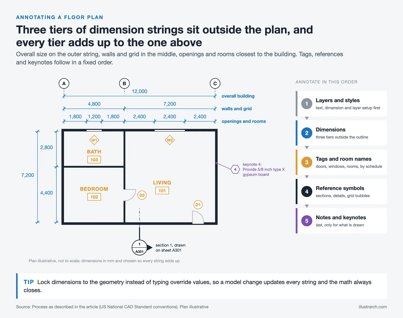
Start with dimensions because they drive everything else. Place dimension strings outside the building outline in tiers: an outer string for the overall building size, a middle string for wall to wall and structural grid spacing, and an inner string for individual openings and room widths. Dimension to the structure, usually face of stud or face of concrete, and stay consistent about that reference across the whole set. For a refresher on placing measurements and reading a plan, the architecture floor plan guide covers how dimension tiers are organized.
💡 Pro Tip
When you dimension, never let two strings give conflicting answers for the same span. A common field problem is an overall dimension that does not equal the sum of its parts. Lock your dimensions to actual geometry rather than typing override values, so any model change updates the number and the math always closes.


Step 3: Add Tags, Labels, and Room Names
Next, tag the elements that connect to schedules. Door and window tags link each opening to a schedule that lists size, type, hardware, and fire rating. Room names and numbers anchor the finish schedule. Keeping tags consistent, with the same shape and numbering logic on every floor, lets a reader cross reference without hunting. This is where architectural drawing notes and labels do the heavy lifting of connecting the picture to the written specification.
Step 4: Place Reference Symbols and Callouts
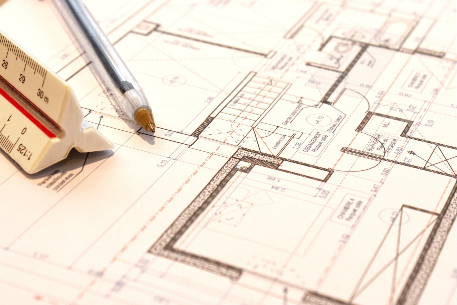
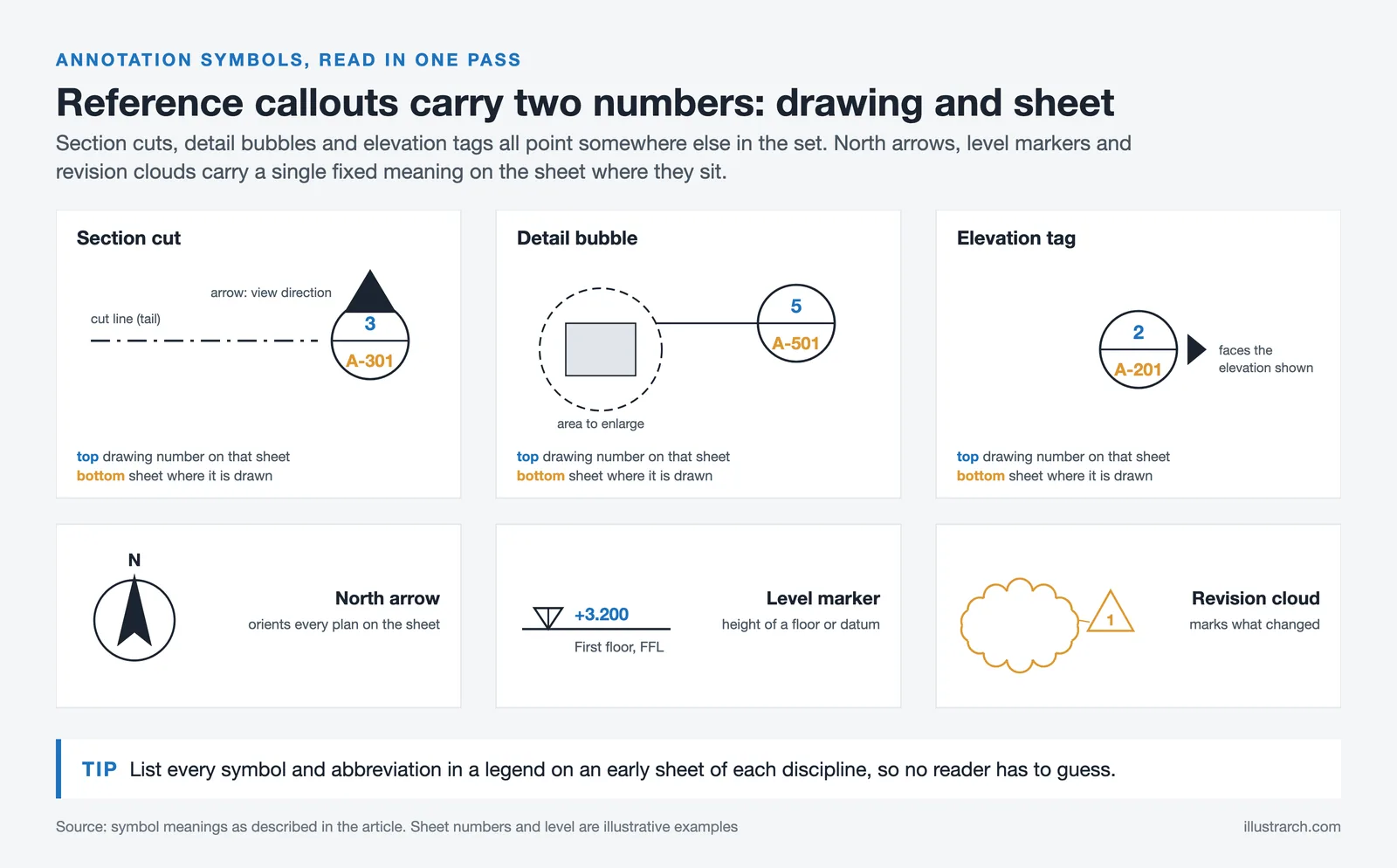
Now add the symbols that route the reader through the set: section cut markers, detail callouts, elevation tags, and grid bubbles. Each one carries two numbers, the detail or sheet number and the sheet it lives on, so the reader can jump straight to the right page. Accurate callouts are what make a set navigable, and they are also the most common source of coordination errors when sheet numbers shift late in a project. If you want to see how these markers guide a reader across disciplines, the guide on how to read construction drawings follows the same trail in reverse.
Step 5: Write Notes and Keynotes Last
Finish with text notes. Use general notes for site wide requirements and keynotes for specific callouts, where a short number on the drawing references a description in a legend. Writing notes last means you annotate only what is actually drawn, and you avoid orphaned notes pointing at geometry that changed. Keep the language imperative and specific: “Provide 5/8 inch type X gypsum board” reads better than a vague description of the wall.

Architectural Annotation Best Practices
The mechanics of placing a note are easy. The discipline is in restraint and consistency. A few habits separate a clean professional set from a cluttered one.
Annotate once, reference everywhere. If a condition repeats, draw and note it in one place as a typical detail, then point to it. Repeating the same long note on twenty walls invites a situation where nineteen get updated and one does not. Keynotes and typical callouts protect you from that drift.
Keep text at a readable plotted height, commonly 3/32 inch or 1/8 inch at the final print scale, and never let annotation overlap linework or other text. Align notes and leaders so they read in tidy columns rather than scattering across the sheet. Use leaders that touch the element they describe with a clear arrow or dot, and avoid crossing leaders where you can. Standard abbreviations belong in a legend on the sheet so a reader is never guessing what a shortened term means.
Scale awareness matters too, because text and symbols are sized for the plotted sheet, not the model. A note that looks fine at full size can become unreadable at 1:100. The relationship between drawing scale and annotation size is worth understanding in depth, and the breakdown of scale in architecture explains why your text height has to be tied to the output scale.
⚠️ Common Mistake to Avoid
Over annotating is as harmful as under annotating. Many drafters bury a plan under so many notes that the geometry disappears and the reader cannot find the one note that matters. The fix is hierarchy: put repetitive requirements in general notes or a typical detail, reserve plan annotation for what is specific to that location, and let white space do its job.

Annotation Symbols, Abbreviations, and Keynotes
Symbols and abbreviations are the shorthand of a drawing set, and they only work when everyone reads them the same way. A section cut symbol, an arrow with a tail and two reference numbers, tells the reader where a section is taken and where to find it. A detail bubble circles an area and points to an enlarged drawing. Elevation tags, north arrows, level markers, and revision clouds each carry a fixed meaning that a standard defines.
Abbreviations save space but cost clarity if they are not declared. Every set should carry a legend listing each abbreviation and symbol with its meaning, usually on an early sheet of each discipline. The annotation symbols in architecture are not arbitrary; most trace back to published conventions, and the closer your set stays to those conventions, the fewer questions you will field during construction.
📐 Technical Note
International drawing conventions for line types, lettering, and presentation are defined in ISO 128, the standard for general principles of representation in technical product documentation. It sets a hierarchy of line weights and a consistent approach to views, which underpins how annotation reads alongside geometry. UK practice references the related BS EN ISO drawing standards for the same purpose.

Linking Annotation to Schedules and Details
Annotation is most powerful when it connects sheets into a single coordinated document. A door tag is meaningless without the door schedule it points to, and a detail callout is dead weight if the referenced detail does not exist or carries the wrong number. This cross referencing is the backbone of a working set. When you create enlarged details, the tag on the plan and the title under the detail have to agree exactly. For more on producing those referenced drawings, see the guide to architectural detail drawings and how they tie back to the plan.
Tools and Standards That Govern Annotation
Whether you draw in AutoCAD, Revit, ArchiCAD, or by hand, the standards behind annotation stay the same; only the mechanics change. In BIM tools, many tags pull data straight from the model, so a door tag reads its size and fire rating from the door object itself. That automation is a strength and a trap: it speeds up tagging, but it also means a wrong parameter in the model produces a confidently wrong note on the sheet.
The authorities worth knowing are few and stable. The American Institute of Architects authored the CAD Layer Guidelines that put annotation on predictable layers and colors. The US National CAD Standard folds those guidelines into a national reference. ISO 128 governs international presentation conventions. For the reasoning behind why these conventions exist, the academic discussion of the conventions of architectural drawing from Carnegie Mellon is a useful read on how drawing became a shared language rather than a personal style.
Drawing standards and annotation conventions vary by office, region, and project type. Always verify the specific requirements of your governing standard and local building authority before issuing a set.

Where to Go From Here
Your Next Step: Open your current working set and audit one sheet against a single standard, checking that dimensions close, tags match their schedules, and every callout points to a real detail. Fixing one sheet to a consistent rule, then applying that rule across the set, will do more for readability than any new software feature.
Frequently Asked Questions
What is the correct order to annotate an architectural drawing?
Set up your annotation layers and text styles first, then add dimensions, followed by tags and room labels, then reference symbols and callouts, and finally written notes and keynotes. Annotating in this order keeps the sheet from getting cluttered early and ensures notes only describe geometry that is actually drawn.
Which standard should I follow to annotate architectural drawings?
In the United States, the US National CAD Standard is the common reference, since it combines the AIA CAD Layer Guidelines with the CSI Uniform Drawing System. Internationally, ISO 128 governs presentation conventions, and UK practice uses the related BS EN ISO drawing standards. Choose the standard your client or jurisdiction requires and apply it consistently across the whole set.
What is the difference between a note and a keynote?
A general note states a requirement that applies broadly across the drawing or project. A keynote places a short number on the drawing that references a fuller description in a legend on the sheet. Keynotes keep the drawing clean by moving long text off the geometry while still linking each callout to a specific, standardized description.
How do I keep annotation readable at different drawing scales?
Size text and symbols for the plotted output, not the model, and tie the text height to the final print scale, commonly 3/32 inch or 1/8 inch. Use annotation scaling features in your software so notes resize correctly when a detail is drawn at a larger scale, and avoid letting text overlap linework or other annotations.
How many dimensions should a floor plan have?
Enough to build the plan without guessing, and no more. Use tiered dimension strings outside the plan: an overall building dimension, a structural grid or wall to wall string, and an interior string for openings and rooms. Avoid duplicate dimensions that can conflict, and make sure each string adds up to the overall measurement.
- annotating architectural drawings
- annotation standards architecture
- annotation symbols in architecture
- architectural annotation best practices
- architectural drawing annotations
- architectural drawing notes and labels
- correct annotation techniques architecture
- how to add notes to architectural drawings
- how to annotate architectural drawings








Foster + Partners to Test Robot Swarms Building Timber from the Top Down
Foster + Partners wins €4m EU grant to build robot and drone...
 illustrarch Editoral Team2 Mins read

PLNAR Review: Does AR Measurement Hold Up on a Real Site Visit?
PLNAR began as a consumer AR tape measure and now runs as...
Sinan Ozen5 Mins read

ArchiSnapper Review: Is This Field Report App Worth It for Architects?
A hands-on look at Deltek ArchiSnapper, the mobile app built for field...
Sinan Ozen5 Mins read

Gross Internal Area and Net Internal Area: What’s the Difference?
The difference between Gross Internal Area and Net Internal Area shapes how...
Sinan Ozen5 Mins read


Leave a comment